


TROUBLESHOOTING
1
1
1- TROUBLESHOOTING TABLE
If a problem has occurred, first inspect the connection of the wiring connector.
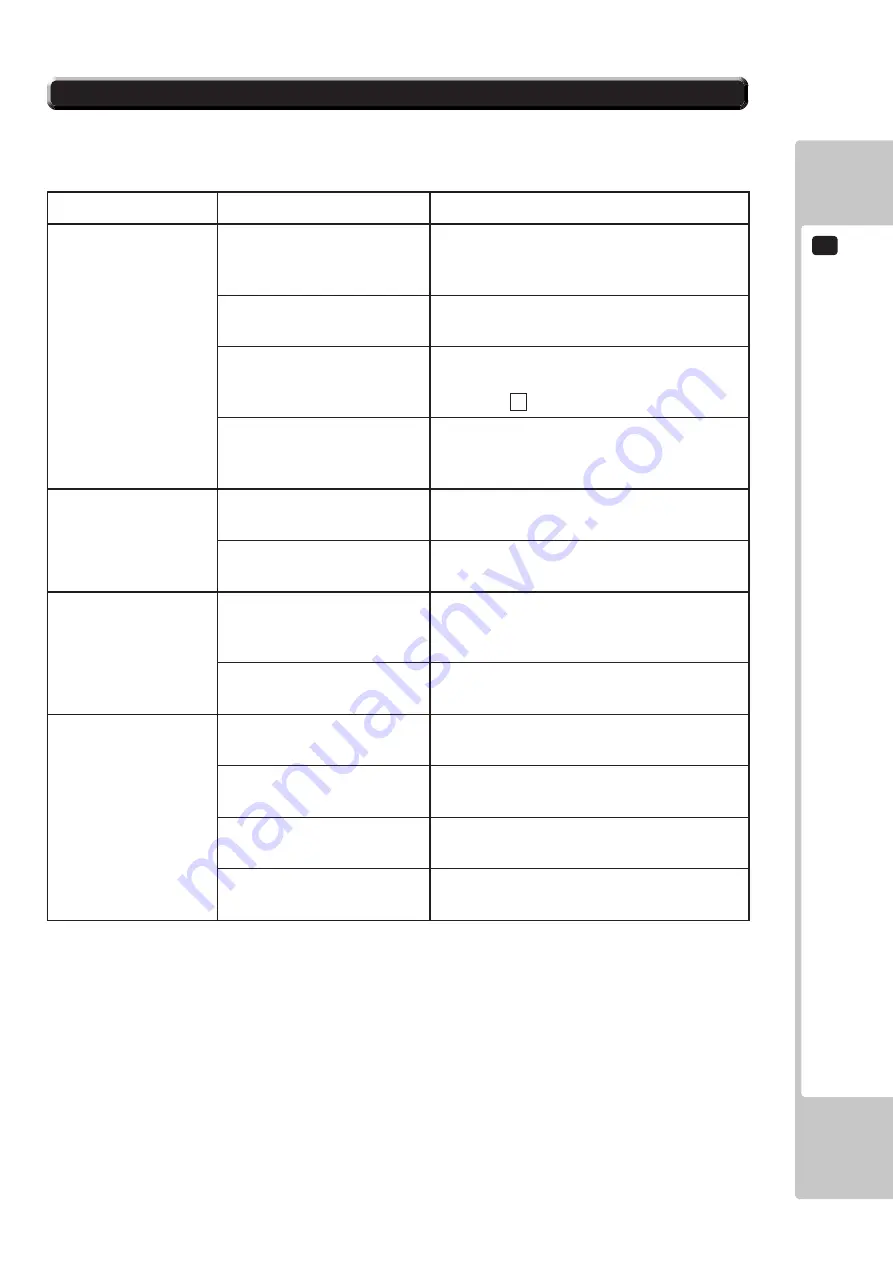
TABLE 17-2
PROBLEMS
CAUSE
COUNTERMEASURES
When the main SW is
turned ON, the machine
is not activated.
The power is not ON.
Firmly insert the plug into the outlet.
Incorrect power source/
voltage.
Make sure that the power supply/voltage are
correct.
The Circuit Protector of the
AC Unit functioned due to
momentary overcurrent.
After eliminating the cause of overload, have the
Circuit Protector of the AC Unit restored. (See
Section 6, 4 , Refer to the following.)
The fuse of the fuse holder was
blown out due to momentary
overcurrent.
After eliminating the cause of overload, replace
the specified rating fuse. (Photo 17-3)
Billboard fluorescent
lamp does not glow.
Faulty connection of
connectors
Join connectors securely between cabinet and
billboard. (See chapter 6-2.)
Fluorescent lamp and glow
lamp need replacement.
Replace the fluorescent lamp and the glow lamp.
(See chapter 15.)
Sounds are emitted and
the lamps are lit, but the
screen is black.
Faulty connections for the
visual signal connector or the
monitor power connector.
Check the connections for the monitor and game
board connectors.
Broken monitor.
Contact the company from whom the unit was
purchased.
Sound is not emitted.
Sound volume adjustment is
not correct.
Adjust the switch unit's sound adjustment
volume. (See 9-1.)
Faulty connections for various
connectors.
Check the connections for the game board, amp,
speakers and volume connectors.
Malfunctioning board,
amplifier and speaker.
Perform output test and check. (See 9-3b.)
Speaker settings are incorrect.
Check the AUDIO OUTPUT setting on the
game setting screen. (See 9-3c.)
Summary of Contents for AFTER BURNER CLIMAX
Page 12: ...1 HANDLING PRECAUTIONS FIG 1b FIG 1c FIG 1d...
Page 50: ...7 PRECAUTIONS WHEN MOVING THE MACHINE 42 FIG 7 1b...
Page 58: ...8 GAME DESCRIPTION 50 FIG 8b FIG 8c...
Page 80: ...EXPLANATION OF TEST AND DATA DISPLAY FIG 9 3a03...
Page 83: ...EXPLANATION OF TEST AND DATA DISPLAY 9 75 FIG 9 3b03...
Page 151: ...TROUBLESHOOTING 17 143 3 Remove the front door FIG 17 3b 4 Replace fuse inside base FIG 17 3c...
Page 176: ...22 PARTS LIST 168 PARTS LIST 22...
Page 181: ...PARTS LIST 22 173 2 ASSY ROLLING BASE ABX 1000 D 1 3 Fastening Torque...
Page 190: ...22 PARTS LIST 182 8 MOTOR UNIT ABX 3200 D 1 2 Fastening Torque...
Page 205: ...PARTS LIST 22 197 22 ASSY MONITOR BOX ABX 1100 D 1 2 Opposite side...
Page 209: ...PARTS LIST 22 201 25 ASSY COINCHUTE TOWER ABX 1200 D 1 2 Coin Box Part...
Page 216: ......
Page 217: ...PARTS LIST 22 209 32 ASSY BILLBOARD ABX 1500 D 1 2...
Page 223: ...PARTS LIST 22 215 36 THROTTLE UNIT ABX W O GRIP 610 0758 D 1 2...
Page 225: ...PARTS LIST 22 217 37 ASSY SEAT UPPER ABX 1700 D 1 2...
Page 233: ...225 WIRING DIAGRAM 24 WIRING DIAGRAM D 1 2 24...
Page 234: ...226 WIRING DIAGRAM 24 D 2 2...