background image


SD-EN-030                                                                31  / 40                                                                  V1.0 

5.


G265 Client User Guide 

After design in the G265 Designer Software has been uploaded successfully into the G265 transceiver, the 
G265 Client can be accessed from devices operated either in Windows, IOS or Android. 

5.1.


Login Window 


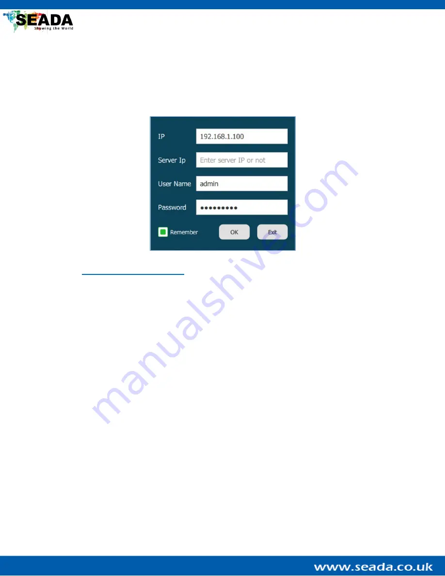
User can run the G265 Client directly without installation. The client can be downloaded from the SEADA 
website (

https://seada.co.uk/downloads

). Run the G265 Client software to get the login dialog box shown 

above.


The default username 

is ‘

admin

’ and the password is ‘

Admin12345

’.

 They can be changed in the G265 

Designer Software. 

By entering the local IP address of the control PC in ‘

IP

’ and clicking ‘

OK

’,

 the G265 Client will be connected 

automatically. If the login is failed, please refer to the troubleshooting section at the end of this document. 

Note that ‘Server Ip’ can be 

left empty as it is for further development. 


Summary of Contents for GENESIS 265

Page 1: ...GENESIS 265 User Guide This user guide provides instructions for setting up SEADA GENESIS 265 using the G265 UMPlatform G265 Designer Software and G265 Client ...

Page 2: ...65 transceiver 4 3 1 Main Tabs 4 3 2 Information Tabs 5 3 3 Sub Tabs Input Encoder TX 6 3 4 Sub Tabs Output Decoder RX 8 4 G265 Designer Software User Guide 10 4 1 Login Window 10 4 2 Designer Menu 11 4 3 Designer Tool Menu 12 4 4 UI Design Area 13 4 5 UI Tool Menu 14 4 6 UI Design UI Menu 15 4 6 1 New Page 16 4 6 2 Rectangle 18 4 6 3 Text 19 4 6 4 Button 20 4 6 5 Slider 22 4 6 6 Signal 23 4 6 7 P...

Page 3: ...g Inputs 29 4 8 3 New Group 29 4 8 4 Group Signal 29 4 9 User 30 4 9 1 New User 30 5 G265 Client User Guide 31 5 1 Login Window 31 5 2 Run G265 Client on the control PC 32 5 3 System Control 33 6 Practical Example 34 7 1 Set up a G265 Client for output panel IPC control audio control and system control 34 7 Troubleshooting 37 Commands for the G265 transceiver 39 ...

Page 4: ...ns Thanks to its standard H 265 264 protocol and low bandwidth requirement The G265 can work with the existing network infrastructure which means there are no needs for dedicated cabling 1 2 Key Features Fanless design no moving parts Supports H 265 264 for high quality AV over IP Supports multi view and matrix switching Supports inputs any size anywhere on screen Supports PoE Supports both digita...

Page 5: ...Diagram Input Output Protocol RTSP Output Format H 265 H264 RS232 Connection Phoenix connector Power Supply 12DC from main power adapter or PoE Audio Input Output Connector Phoenix connector Audio Input Format Unbalanced Operating Temperature Range 0 40 degrees centigrade Operating Humidity Range 10 90 non condensing Storage Temperature Range 20 60 degrees centigrade Storage Humidity Range 10 90 n...

Page 6: ... 3rd party RTSP IP sources such as IP cameras and 3rd party encoders into the same IP switch as the G265 transceiver with CAT6 or higher 6 Connect any other 3rd party devices to the G265 transceiver or to the IP switch 7 Connect the control PC to the same IP switch as the G265 transceiver 2 2 Ethernet LAN connection with the control PC The default static IP address of the G265 transceiver is 192 1...

Page 7: ... the current Input Output list Restart Restart all the selected devices Select All Select all the devices in the current Input Output list Reverse Select Reverse select the devices in the current Input Output list Scan Setting Bind the local IP address of the control PC to scan the devices If the device is not displayed in the list after pressing Scan use this button to bind the device and scan ag...

Page 8: ...SD EN 030 5 40 V1 0 3 2 Information Tabs This tab contains information about the G265 transceiver Input Output IP The IP address of the device Firmware Version The firmware version of the device ...

Page 9: ...ss Encoding setting Config settings for the mainstream and substream of the device Audio setting Config the audio setting for the encoder The default setting is 3 5mm corresponding to the ports on the back of the device User can change it to HDMI to use the HDMI port I O setting User can set up the encoder to control third party devices This includes system control via RS232 RS485 I O IR TCP IP an...

Page 10: ...em Info The information of the device As Switch to output function is no longer being used user needs to toggle the switch on the back of the G265 transceiver and restart it to switch between encoder and decoder System query Display the system log of the selected device Firmware Update Update the firmware of the selected G265 transceiver Note that this function is only visible when the software is...

Page 11: ...r The default setting is 3 5mm corresponding to the ports on the back of the device User can change it to HDMI to use the HDMI port I O setting User can set up the decoder to control third party devices This includes system control via RS232 RS485 I O IR TCP IP and Relay Led setting Config the device for the use of LED screen Advanced setting Config the functions of the selected G265 transceiver D...

Page 12: ...mation of the device As Switch to output function is no longer being used user needs to toggle the switch on the back of the G265 transceiver and restart it to switch between encoder and decoder System query Display the system log of the selected device Firmware Update Update the firmware of the selected G265 transceiver Note that this function is only visible when the software is full screen ...

Page 13: ... Designer Software will fail to run PLEASE re download the software package from our website https seada co uk downloads if above occurs Before login user needs to change the IP address of the control PC to a static IP address and the same network segment as the G265 transceiver 192 168 1 208 at TCP IPv4 in Ethernet Properties IP address any address between 192 168 1 2 and 192 168 1 254 except the...

Page 14: ...d it contains all the functions supported by the G265 transceiver UI Design Contain components to build up the User Interface UI for the G265 Client Panel Setting Config the output panel and its audio settings Input Setting Scan and manage input signals User User management for the G265 Client ...

Page 15: ...e functions that require the connection to the G265 transceiver such as setting up the output panel and PTZ IP camera control cannot be tested under this mode Clear then New Clear the current UI design and create a new one Open Open an existing design Save as Save the current design into a txt file Download Download the design from the connected G265 transceiver Upload Upload the current design to...

Page 16: ...the G265 Client are created The layout of the UI in the G265 Client will follow the design in the UI Design Area On the top right of the area there are three buttons Logout Min and Exit They are only accessible in the G265 Client for loging out minimising and exiting the G265 Client ...

Page 17: ...Align the selected components horizontally centred Right Align Align the selected components to the right Top Align Align the selected components to the top Vertical Align Align the selected components vertically centred Bottom Align Align the selected components to the bottom Horizontal Array Symmetrise the selected components horizontally Vertical Array Symmetrise the selected components vertica...

Page 18: ...menu contains components to build up the UI for the G265 Client Except New Page all components can be dragged dropped onto the UI Design Area to be created All the UI components can also be deleted by clicking Del on the keyboard after being selected ...

Page 19: ...SD EN 030 16 40 V1 0 4 6 1 New Page ...

Page 20: ...Move the current page down by one Copy a Page Copy the current page and paste a new one below it Copy to End Copy the current page and paste a new one at the end of the page list Export Export the current page to a pag file and this page can be imported via Open in the Designer Tool Menu Delete Page Delete the current page Note that the global page cannot be deleted Global Setting Menu Configurati...

Page 21: ...l component in the UI Design Area selecting the rectangle component holding Ctrl and dragging the component into the rectangle component will bind them together Afterwards in the G265 Client when there are a large number of input signals user can use this rectangle component to search the specific input signal from the signal group list or signal component by entering the name of the signal Fill C...

Page 22: ...sted by dragging the yellow adjustment box around the component in the UI Design Area Text Change the format of the texts in the text box such as the font size and colour The text can also be rotated at different angles In the case that time information is required in the G265 Client the text component can be set in a time format displaying the system time of the control PC ...

Page 23: ...utton In the G265 Client when the button is clicked the component will become visible and when it is clicked again it will become invisible By setting multiple buttons in the same Group setting them to the same Group Button number only components bound to the same button will be visible at a time while others are invisible depending on the button being pressed User can also config the mode of the ...

Page 24: ...nding on its state the G265 transceiver can send out commands to a third party device to control it The function for each state for example Normal and Push can be set separately Fill Change the colour or background design of the button The design for each state of the button can be set separately Text When Show Text is triggered this section will be expanded and user can modify the texts and their...

Page 25: ...cal direction It can also be set in the form of a knob By ticking Show text a percentage marker can be displayed by the slider representing the value change of the slider User can also set the min max value of the slider and its divides The sliders can be assigned to different channels by entering a number in the channel sections Fill Change the colour or background design of the slider In the Lin...

Page 26: ...o the panel from the signal component In the G265 Client the text signal in each preview tab will be replaced by the name of the input signal set up in Input Setting The format of this text including the size and colour as well as the size of the preview tab can be changed in this section Scroll Bar Change the width and colour of the scroll bar Label Change the size and text colour of the signal g...

Page 27: ... onto the screens of the cloned panel the same content will be displayed on screens of the original panel When Screen Edge is unticked the grids on the output panel will be invisible Toolbar By default the tool bar is located on the bottom of the panel and it can be changed Multiple function buttons are available on the toolbar and user can change the size colour and visibility of them More detail...

Page 28: ...l the input signals in this group will show in the list User can use this list to switch the input signal Note real time preview of the input signals is not available when using the list component User can also change the format of the items in the list such as the size and space between different items Useful tools like check boxes and tool buttons can also be added to the list components Selecte...

Page 29: ... Attribute The get back component can be set either in a horizontal or a vertical direction It can also be set in the form of a knob By ticking Show text a value marker can be displayed by the get back component representing the value change of the component User can also set the min max value for it Fill Change the colour or background design of the get back component In the Link tab user can set...

Page 30: ...text format can also be changed Toolbar Change the format of the toolbar on the bottom of the matrix component Fill Change the colour or background design of the matrix component By clicking on either inputs or outputs in the matrix component in the Link tab user can bind the transceiver to a specific input output User can also set customised inputs as inputs for the matrix component Note that whe...

Page 31: ...licking Add the panel will light up and user can then config the mode Basic Attribute User can change the name of the current mode By entering contents in the form of AxB for example 2x3 the output panel will be divided into 2 rows and 3 columns by grids To disable a mode enter 0x0 in Divide Position Size When one window in the output panel is selected the position and size of this window can be m...

Page 32: ...al groups depending on their requirement The name of the signal group can be changed by double clicking the name Each signal group can be assigned with different input signals respectively by ticking the input signals in the Input List To delete a signal group simply choose it and click X on the right Note that to add new groups into the signal componet user needs to click on singal component and ...

Page 33: ... 9 1 New User By clicking New user the system can add a new user level This user level can be assigned with permissions to access different pages of the G265 Client output panels and input singal groups After all settings in the G265 Designer Software have been completed click Upload on the top right of the software and click OK When a pop up shows Upload succeed that means the setting for the G26...

Page 34: ...downloaded from the SEADA website https seada co uk downloads Run the G265 Client software to get the login dialog box shown above The default username is admin and the password is Admin12345 They can be changed in the G265 Designer Software By entering the local IP address of the control PC in IP and clicking OK the G265 Client will be connected automatically If the login is failed please refer t...

Page 35: ...customised grid layouts 2x2 3x3 and 4x4 Multiview Preset Preset the output panel offline Publish Apply the offline preset layout onto the output panel Text Display scrolling texts on the output panel Refresh Restore the output preview in the G265 Client to match the output panel Clear Clear the current output panel By double clicking the output panel when there is no window on it user can choose a...

Page 36: ...oftware User Guide there are many other components that can be added to the G265 Client User can set up the G265 transceiver to control third party devices This includes system control via RS232 RS485 I O IR TCP IP and Relay Below are some examples TV Control TV Control allows user to use the G265 Client as a remote controller to operate the TV using the infrared serial port on the G265 transceive...

Page 37: ...tting user can change the network parameters such as IP address and name for the G265 transceiver if necessary G265 Designer Software 5 Run G265 Designer Software and click on the control PC IP address in the login dialog box Output Panel 6 Double click the output panel In Panel Setting choose GENESIS 265 from the Panel list on the left 7 Bind the G265 transceiver with the output by choosing the d...

Page 38: ... 2 Recall Preset 3 and Recall Preset 4 21 After all buttons in IPC 1 Control Panel is set up user needs to select button 1 hold Ctrl button on the keyboard and bind this control panel with button 1 by dragging the IPC 1 Control Panel into the button Audio Control 22 Go back to Panel Setting click on audio follow on the right of the menu and click on add new User can set up the transceiver to proce...

Page 39: ...onal There are multiple buttons preset for customise and user can use these buttons or add more buttons for different use 33 Optional User can also add more pages with extra components to achieve more functions such as audio matrix switch and light switch control panel Design Upload 34 When everything is set up click Upload on the top right of the G265 Designer Software and click OK 35 When a pop ...

Page 40: ... in the G265 Designer Software 1 Check if all the devices are correctly connected using the G265 UMPlatform and the G265 Designer Software 7 4 G265 Client connection failed Download resource failed please reload 1 Check if all the devices are correctly connected using the G265 UMPlatform and the G265 Designer Software 2 Check if the username password and IP address are correct 3 Ensure that there ...

Page 41: ...equreiment 7 9 Outputs on the output panel does not perform properly 1 Ensure that the resolution of the outputs on the output panel does not exceed the decoding limitation of the transceiver 2 Ensure that the IP switch and CAT meets the minimum requirement as specified 7 10 The Default Design is disarranged and not working anymore 1 Open the file called Draft_0 in the downloaded software package ...

Page 42: ...he saved layout Scene_ID The name of the layout that can be viewed in the G265 Client For example SaveScene 600001 001 L01 Save the current layout for output panel 600001 as layout ID 001 of which the name is L01 Recall Layouts CallScene Panel_ID Scene_ID Panel_ID The UUID of the output panel which can be found in the G265 Designer Software starting from 600001 Scene_ID The ID for the saved layout...

Page 43: ...e Panel_ID Scene_ID Panel_ID The UUID of the output panel which can be found in the G265 Designer Software starting from 600001 Scene_ID The ID for the saved layout For example DeleteScene 600001 001 Delete the layout ID 001 for output panel 600001 Get layouts IDs GetSceneNames Panel_ID Panel_ID The UUID of the output panel which can be found in the G265 Designer Software starting from 600001 For ...

Reviews: