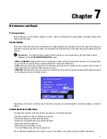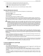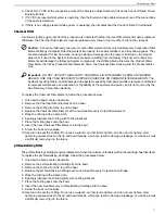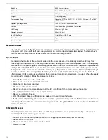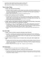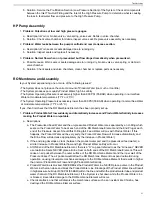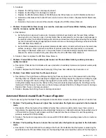
Salinity Probe
The salinity probe requires cleaning when debris builds up on the monel probes. Clean the probes once a year
according to the procedures below.
1. Unscrew the black tube fitting nut (below the probe) to disconnect it from the control manifold.
2. Using a soft bristle brush, scrub the probes to remove any built up debris.
3. Thoroughly dry the probe area.
4. Should the salinity reading become inaccurate, replace the probe.
3-way Product Water Diversion Solenoid Valve
Note:
Do not assume that the valve’s solenoid is non-operational. Check it by performing a function test as
described in the topic
Manual System Check
on page 43.
Caution:
Over tightening the tube fittings can cause the diversion valve's internal ports to move out of the
proper position, thereby causing internal blockage or bypass.
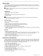
Follow the steps below to check the diversion valve for problems.
1. Remove Diversion Valve from the system.
2. Position the
Manual Override
button
OUTWARD
(to the normal position) by first pushing the button inward
and then rotating counter clockwise, allowing it to spring outward and away from the coil body.
3. With your mouth, blow into port “P.” Air should expel from port “B,” which is the “normally open” or “bad water”
port.
a. If you encounter significant resistance when attempting to expel air from port “B” (or if no air expels from
port “B”), then replace the valve.
4. Blow into port “P” again, while plugging port “B” with your fingertip. No air should expel from port “A.”
a. If air expels from port “A”, then replace the valve.
5. Position the
Manual Override
button
INWARD
(to the manual override position) by first pushing the button
inward and then rotating it clockwise, allowing it to lock inward (close to the coil body).
6. With your mouth, blow into port “P.” Air should expel from port “A,” which is the “normally closed” or “good water”
port.
a. If you encounter significant resistance when attempting to expel air from port “A” (or if no air expels from
port “A”), then replace the valve.
7. Blow into port “P” again, while plugging port “A” with your fingertip. No air should expel from port “B.”
a. If air expels from port “B,” then replace the valve.
Follow the steps below to check the condition of the Diversion Valve solenoid coil.
Note:
The 3-way Product Diversion Valve Solenoid operates from 12 VDC.
1. While the System is operating and producing potable water, use a voltmeter (set to DC) to check the voltage
at the din connector terminals (top of solenoid).
2. If 12 VDC is present at the din connector terminals, then the control circuit is operating normally; however, the
3-way Diversion Valve Coil may be shorted or open. Check the solenoid coil continuity. Note that this check
can only be performed when the solenoid is electrically disconnected from the Control Board.
3. Remove the din connector from the solenoid. Using an Ohm meter, measure the continuity of the solenoid coil
as shown below.
4. If an open circuit exists, or if the resistance is much greater than (or less than) 12 to 15 ohms, then replace the
solenoid coil or the entire valve.
5. If 12 VDC is not present at the din connector terminals, then the cable connections may be loose, the cable
may be broken, or the control circuit may be inoperable. Check these components.
Aqua Matic XL 2200 - 3600
70
Summary of Contents for Aqua Matic XL Series
Page 2: ......
Page 10: ......
Page 28: ......
Page 38: ......
Page 45: ...45 Commissioning...
Page 46: ......
Page 58: ......
Page 76: ......
Page 89: ...Chapter 10 Appendix 89...
Page 90: ...ABS Certificate of Design Assessment Aqua Matic XL 2200 3600 90...
Page 91: ...FCC Compliance 91 Appendix...
Page 92: ...DNV ISO 9001 Certificate Aqua Matic XL 2200 3600 92...
Page 93: ...Single Phase Electrical Motor Wiring 93 Appendix...
Page 94: ...Three Phase Electrical Motor Wiring Aqua Matic XL 2200 3600 94...
Page 95: ...Three Phase Transformer Wiring 95 Appendix...
Page 96: ...New System Initial Readings Form Aqua Matic XL 2200 3600 96...
Page 97: ...Daily System Readings 97 Appendix...
Page 98: ......
Page 99: ...Chapter 11 Exploded Parts Views 99...
Page 100: ...Exploded Parts View...
Page 103: ...7 8 9 10 11 12 13 14 15 16 17 20 19 18 21 22 23 24 25 26 1 2 3 4 5 6 Exploded Parts View 4...
Page 111: ...14 13 2 16 13 12 3 8 10 9 7 1 5 4 6 14 13 15 15 17 13 12 11 18 15 Exploded Parts View 12...
Page 113: ...19 16 2 21 16 14 3 9 11 10 8 1 5 4 6 12 22 20 18 16 17 15 15 13 7 Exploded Parts View 14...
Page 115: ...2 3 10 12 11 9 1 5 4 21 13 20 18 15 19 18 19 15 17 14 16 8 18 15 7 Exploded Parts View 16...
Page 117: ...10 26 11 9 5 5 4 20 1 7 18 3 2 16 13 15 12 14 13 23 24 21 24 25 Exploded Parts View 18...
Page 119: ...12 10 13 11 5 5 4 6 1 9 20 3 2 17 16 14 18 15 19 17 16 14 18 15 8 7 Exploded Parts View 20...
Page 128: ...6 7 2 3 2 5 10 10 12 1 11 8 9 8 11 6 7 4 2 13 14 29...
Page 138: ...Chapter 12 Electric Diagrams Foldouts 101...
Page 139: ...Aqua Matic XL Series Three Phase Wiring Diagram...
Page 140: ......
Page 141: ......


