d. Ensure all three phases have power.
3.
Problem: The Electric Motor makes an unusual “grinding” sound when operated.
a. Solutions:
a. Check to see if the fan is rubbing against the fan guard.
b. Replace motor, as required.
4.
Problem: The High Pressure Pump makes an unusual “grinding” sound when operated.
a. Description: The pump will make a grinding noise if its drive shaft has been forced into the pump body. The
Electric Motor and Pump are coupled with a “Flex Coupler” specially designed for use with this specialized
pump. Never replace the Flex Coupler with another make or style. ALWAYS leave 3/32 in. (2mm) spacing
between the two mating Flex Couplers. ALWAYS ensure that the Safety Bell Housing attached to the electric
motor and the pump seats evenly on both ends. Internal spacing of moving components within the High
Pressure Pump hold to very tight tolerance. Any debris larger than 10 micron entering the High Pressure
Pump will cause abrasion to the pump’s internal parts, and will cause an audible grinding noise. Hard debris,
such as sand or metal, will cause the pump to “freeze up” and will cause extensive damage to the internal
parts of the pump. If the System incorporates a Multi Media Filter use caution to not allow sand to enter the
High Pressure Pump. When changing Prefilter Elements use caution to not allow debris to enter the High
Pressure Pump. Damage to the High pressure Pump caused by debris is the responsibility of the person
performing maintenance to the System, is the liability of the person performing maintenance to the System,
and is not covered by the Sea Recovery warranty.
b. Solutions:
a. Check spacing between the motor’s and pump’s flex coupler. Spacing must be minimum 3/32 in. (2mm)
and maximum 1/8 in. (3mm).
b. Check Safety Bell Housing to ensure it is flush and secured to both the motor and pump.
c. Check Pump for signs of foreign debris entering the inlet.
5.
Problem: Decreased Pressure
a. Description: The High Pressure Pump flow and or pressure have decreased from normal. As with all High
Pressure Pumps, over time of operation flow and pressure will decline due to internal wear. Under normal
use and care no significant pressure or flow loss will occur for 8,000 hours of operation or longer. Do not
confuse low feed water flow and low feed water pressure with a High Pressure Pump problem. All positive
displacement pumps must receive a specific flow at a minimum pressure else cavitation will occur. Check
to ensure that the Booster Pump is delivering at least 4.5 U.S. Gallons (17 Liters) Per Minute of feed water
at 10 to 40 PSI (69 to 276 kPa) at the Inlet of the High Pressure Pump. Note: Systems operating on 50 Hz
power will deliver 3.75 U.S. Gallons (14.2 Liters) Per Minute of feed water.
b. Solution: If Feed Water Flow and Pressure into the High Pressure Pump are within minimum specifications,
and if the electric motor is rotating at the proper rotation (the proper cycles are present from the power
source) yet the High Pressure Pump has lost Flow and or Pressure then return the High Pressure Pump to
Sea Recovery for servicing.
6.
Problem: Leaks between Pump and Motor
a. Description: The High Pressure Pump leaks water between the pump and motor. The HP Pump has a
ceramic and carbon seal. Ceramic and carbon seals will weep if the pump is not operated for extended
periods of time. When used regularly the seal will give approximately 8,000 hours of use. The seal continually
wears during use and must be replaced approximately every 8,000 hours or at the sign of leakage.
b. Solution: Return the High Pressure Pump to Sea Recovery for service and Seal replacement.
7.
Problem: Knocking Noise
a. Description: The High Pressure Pump makes an unusual and loud “knocking” noise. All positive displacement
pumps will make a very loud knocking noise if they do not receive sufficient flow at a positive pressure. This
knocking noise results from cavitation which is caused by insufficient feed water flow at an insufficient
pressure.
Aqua Matic XL 2200 - 3600
82
Summary of Contents for Aqua Matic XL Series
Page 2: ......
Page 10: ......
Page 28: ......
Page 38: ......
Page 45: ...45 Commissioning...
Page 46: ......
Page 58: ......
Page 76: ......
Page 89: ...Chapter 10 Appendix 89...
Page 90: ...ABS Certificate of Design Assessment Aqua Matic XL 2200 3600 90...
Page 91: ...FCC Compliance 91 Appendix...
Page 92: ...DNV ISO 9001 Certificate Aqua Matic XL 2200 3600 92...
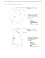
Page 93: ...Single Phase Electrical Motor Wiring 93 Appendix...
Page 94: ...Three Phase Electrical Motor Wiring Aqua Matic XL 2200 3600 94...
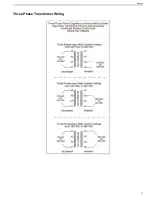
Page 95: ...Three Phase Transformer Wiring 95 Appendix...
Page 96: ...New System Initial Readings Form Aqua Matic XL 2200 3600 96...
Page 97: ...Daily System Readings 97 Appendix...
Page 98: ......
Page 99: ...Chapter 11 Exploded Parts Views 99...
Page 100: ...Exploded Parts View...
Page 103: ...7 8 9 10 11 12 13 14 15 16 17 20 19 18 21 22 23 24 25 26 1 2 3 4 5 6 Exploded Parts View 4...
Page 111: ...14 13 2 16 13 12 3 8 10 9 7 1 5 4 6 14 13 15 15 17 13 12 11 18 15 Exploded Parts View 12...
Page 113: ...19 16 2 21 16 14 3 9 11 10 8 1 5 4 6 12 22 20 18 16 17 15 15 13 7 Exploded Parts View 14...
Page 115: ...2 3 10 12 11 9 1 5 4 21 13 20 18 15 19 18 19 15 17 14 16 8 18 15 7 Exploded Parts View 16...
Page 117: ...10 26 11 9 5 5 4 20 1 7 18 3 2 16 13 15 12 14 13 23 24 21 24 25 Exploded Parts View 18...
Page 119: ...12 10 13 11 5 5 4 6 1 9 20 3 2 17 16 14 18 15 19 17 16 14 18 15 8 7 Exploded Parts View 20...
Page 128: ...6 7 2 3 2 5 10 10 12 1 11 8 9 8 11 6 7 4 2 13 14 29...
Page 138: ...Chapter 12 Electric Diagrams Foldouts 101...
Page 139: ...Aqua Matic XL Series Three Phase Wiring Diagram...
Page 140: ......
Page 141: ......


