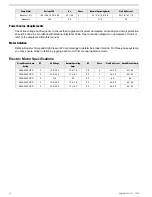
heads facing the same direction. Using fine sandpaper, remove any flash from the hose-barb fittings. If your
System is not supplied with one or more of the optional components mentioned, then skip it and make a
connection to the next supplied component.
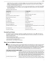
2. Using the supplied 50 feet (15 meters) of ½ in. (12.7 mm) ID, clear, braided hose, connect the Product Water
Line components. Secure each connection with the supplied hose clamps, placing one (1) hose clamp onto
each hose-barb fitting.
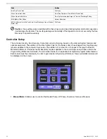
Component Interconnect Chart
To Component Inlet
Component Outlet
Sea Strainer
Inlet Connection
Rinse Clean Inlet Valve left or right port
Sea Strainer
Rinse/Clean Container
Rinse Clean Inlet Valve unused left or right port
Booster Pump
Rinse Clean Inlet Valve center port
Pre-filtration Options
Booster Pump
LP Manifold
Pre-filtration Options
Rinse Clean Discharge Valve
Brine Discharge Tee
Cleaning Bucket
Rinse Clean Discharge Valve
Brine Discharge Connector
Rinse Clean Discharge Valve
Multi Media Filter Discharge Fitting separate Thru-Hull or Tee at Brine
Discharge Connector
Multi Media Filter Waste Line (if used)
Ultra Violet (UV) Sterilizer
pH Neutralizing Filter
Potable Water Storage Tank or Cistern
Ultra Violet (UV) Sterilizer
Remote Touch Screen
The Remote Touch-Screen Enclosure Assembly is supplied with an 80 ft (24.4 m) long, NMEA-200 cable for
connection to the Main Control Panel. Place and install the Remote Touch-Screen Enclosure in a location that
meets the following criteria:
• Away from water lines and hoses.
• Away from locations that could be sprayed with water.
• In an accessible and viewable location.
• Within 80 ft (24.4 m) of the Main Control Panel.
Water Tank and Optional Components
Note:
These optional components are installed inside the Fresh Water Tank. The high- and low-level tank
switches are not mandatory for System operation; however, they do add features when the System is in
Automatic mode. The choice of make, model and style are left up to the Installer and/or Owner. The switches
must meet the electrical requirements and operations described below. The Installer may also connect an
optional
, external alarm to the System, which will alert the Operator when the System shuts down.
Description
Optional Component
(Owner/Installer-supplied)
Provides an
optional feature
to the System Control Logic that works in conjunction with the
Automatic Fresh Water Flush option. When installed and connected to the Main Printed Circuit
Fresh Water Tank Low Level Switch
Board, the Fresh Water Tank Low-Level Switch must be connected as a Normally Open (NO),
One Pole Single Throw (1PST) switch. When the Fresh Water Tank is empty, the switch is
open. As water rises in the tank, the switch closes. This informs the System Control Logic that
there is sufficient Fresh Water to perform the Automatic Fresh Water Flush Cycle.
Provides an
optional feature
to the System Control Logic that allows the System to shut off
automatically when the Fresh Water Tank is full (as long as the System is operating in Automatic
Fresh Water Tank High Level Switch
33
Installation
Summary of Contents for Aqua Matic XL Series
Page 2: ......
Page 10: ......
Page 28: ......
Page 38: ......
Page 45: ...45 Commissioning...
Page 46: ......
Page 58: ......
Page 76: ......
Page 89: ...Chapter 10 Appendix 89...
Page 90: ...ABS Certificate of Design Assessment Aqua Matic XL 2200 3600 90...
Page 91: ...FCC Compliance 91 Appendix...
Page 92: ...DNV ISO 9001 Certificate Aqua Matic XL 2200 3600 92...
Page 93: ...Single Phase Electrical Motor Wiring 93 Appendix...
Page 94: ...Three Phase Electrical Motor Wiring Aqua Matic XL 2200 3600 94...
Page 95: ...Three Phase Transformer Wiring 95 Appendix...
Page 96: ...New System Initial Readings Form Aqua Matic XL 2200 3600 96...
Page 97: ...Daily System Readings 97 Appendix...
Page 98: ......
Page 99: ...Chapter 11 Exploded Parts Views 99...
Page 100: ...Exploded Parts View...
Page 103: ...7 8 9 10 11 12 13 14 15 16 17 20 19 18 21 22 23 24 25 26 1 2 3 4 5 6 Exploded Parts View 4...
Page 111: ...14 13 2 16 13 12 3 8 10 9 7 1 5 4 6 14 13 15 15 17 13 12 11 18 15 Exploded Parts View 12...
Page 113: ...19 16 2 21 16 14 3 9 11 10 8 1 5 4 6 12 22 20 18 16 17 15 15 13 7 Exploded Parts View 14...
Page 115: ...2 3 10 12 11 9 1 5 4 21 13 20 18 15 19 18 19 15 17 14 16 8 18 15 7 Exploded Parts View 16...
Page 117: ...10 26 11 9 5 5 4 20 1 7 18 3 2 16 13 15 12 14 13 23 24 21 24 25 Exploded Parts View 18...
Page 119: ...12 10 13 11 5 5 4 6 1 9 20 3 2 17 16 14 18 15 19 17 16 14 18 15 8 7 Exploded Parts View 20...
Page 128: ...6 7 2 3 2 5 10 10 12 1 11 8 9 8 11 6 7 4 2 13 14 29...
Page 138: ...Chapter 12 Electric Diagrams Foldouts 101...
Page 139: ...Aqua Matic XL Series Three Phase Wiring Diagram...
Page 140: ......
Page 141: ......


