background image

Repairing Leaks

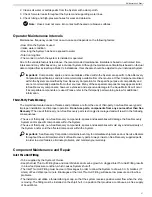
If both ends of the quartz sleeve are leaking, perform the following procedures on both ends:
1. Use a channel lock to loosen and remove the compression nut.

2. Remove the quartz sleeve O-ring (without pulling the quartz sleeve out).

3. Lubricate the quartz sleeve tip with clean water and place new O-ring. Ensure the O-ring makes consistent

contact with the cylinder pass-thru.

4. Replace and tighten the compression nut.

5. Refill the treatment chamber and verify leak-free conditions.

Measuring Performance

Every UV unit must be tested periodically to verify efficiency. Regardless of the intended application or any optional

equipment provided with the UV unit, the most accurate procedure is a Post-UV Analysis. The Post-UV Test must

be performed in accordance with standard testing methods.

Verifying Lamp Operation

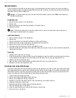
The UV lamp is

ON

when blue light is emitting thru the viewport.

Obtaining Water Samples

The vast majority of unsatisfactory Post-UV Test results are directly related to improper sample-taking techniques.

Although several commercial sample collection apparatuses are available, proper manufacturer’s procedures must

be followed.
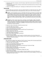
1. Use sterile sample bottles (obtained from reliable laboratory) that have been autoclaved and stored in plastic.

2. Use a temporary tube to direct water from the UV unit to a container or drainage.

3. Pressurize the UV unit and flush unit with sample valve that is fully opened for 3.5 minutes. Sea Recovery

Corporation recommends using a valve that has a discharge orifice smaller than ¼” (6mm). After flushing for

3.5 minutes, reduce valve opening to 50% and flush for 3 minutes.

4. Open the sample bottle and keep the inside of the cap face-down.

5. Fill the sample bottle and avoid breathing directly into the bottle or touching the inside of the bottle, cap and

neck.

6. Immediately cover and secure the cap after filling the sample bottle.

7. Label the sample bottle and place in a clean plastic bag.

8. Take sample bottle to the laboratory for plating as soon as possible.

Important:

Sample processing must begin within three hours after sample collection and must comply with

accepted standard methods.

75

Maintenance and Repair

Summary of Contents for Aqua Matic XL Series

Page 1: ...atic XL Compact Modular 2200 3400 Owner s Manual SYSTEM MODELS New Release April 2016 SRC Aqua Matic 2200 SRC Aqua Matic 2600 SRC Aqua Matic 2800 SRC Aqua Matic 3400 Manual PN B6513100001 Revision 4 2...

Page 2: ......

Page 3: ...Chemical 15 Sea Recovery SRC MCC 3 Membrane Cleaning Chemical 16 Patent Information 16 Chapter 2 System Description 17 Pre Installation Safety Checks 17 Storage Prior to Uncrating 17 Chemical Precauti...

Page 4: ...39 System Valve Positions 39 Controller Setup 40 Manual System Check 43 Multi Media Filter Backwash and Rinse 44 Chapter 6 General Operation 47 Important Notes 47 New Systems 47 Freezing Temperature...

Page 5: ...ector 69 Brine Discharge Connector 69 Multi Media Filter Waste and Brine Discharge Tee 69 Thru Hull Discharge Fitting 69 Product Water T Collector 69 Salinity Probe 70 3 way Product Water Diversion So...

Page 6: ...91 DNV ISO 9001 Certificate 92 Single Phase Electrical Motor Wiring 93 Three Phase Electrical Motor Wiring 94 Three Phase Transformer Wiring 95 New System Initial Readings Form 96 Daily System Reading...

Page 7: ...y on are typically correctable Note that if a minor component problem is left uncorrected it can affect the rest of the system and lead to more extensive issues and or damage Important Sea Recovery en...

Page 8: ...e laws and regulations pertaining to the use of this manual In addition the use of this manual forms an agreement that Sea Recovery s trademarked name or Sea Recovery s trademarked logo mark are not t...

Page 9: ...sion republication display or performance of the content within this manual is strictly prohibited Copyright Sea Recovery Corporation 2008 2012 Revision History Description Affected Pages Date Rev Ini...

Page 10: ......

Page 11: ...operator With one touch the Aqua Matic XL will start and finish water production automatically Inside this manual you will find detailed technical information and instructions for the installation op...

Page 12: ...to repair or replacement of the at Sea Recovery Corporation s discretion Under no circumstances is Sea Recovery Corporation liable for consequential damages arising out of or in any way connected with...

Page 13: ...d equipment Obtaining Warranty Service To obtain warranty service the defective product or part must be returned to an authorized Sea Recovery Corporation Service Center or direct to Sea Recovery Corp...

Page 14: ...environmental regulations Compliance Sea Recovery s Reverse Osmosis Desalination Systems are Type Accepted by the American Bureau of Shipping ABS Sea Recovery s Reverse Osmosis Desalination Systems co...

Page 15: ...SICIAN DO NOT INDUCE VOMITING GIVE ONE GLASS OF TAP WATER OR MILK IN CASE OF CONTACT IMMEDIATELY FLUSH EYES WITH WATER FOR 15 MINUTES GET IMMEDIATE MEDICAL ATTENTION THOROUGHLY WASH AFFECTED SKIN AFTE...

Page 16: ...IATELY FLUSH EYES WITH WATER FOR 15 MINUTES GET IMMEDIATE MEDICAL ATTENTION THOROUGHLY WASH AFFECTED SKIN AFTER HANDLING PRODUCT CONTACT A PHYSICIAN IF IRRITATION PERSISTS MEDICAL PERSONNEL FAMILIAR W...

Page 17: ...XL that may contain any of the following chemicals Hydrogen peroxide chloramines T Chlorine dioxide chlorine Bromine phenolic disinfectants Chloramines N chlorioisocyanurates Hypochlorite iodine Brom...

Page 18: ...ount the liquid holding component above any electrical or electronic device Extensive damage to the electronic device will result if liquid enters device during maintenance and or component failure Im...

Page 19: ...water temperature Product water temperature Automatic computer controlled electronic monitoring The salinity monitoring components of the system give a continuous readout in micromhos per cubic centim...

Page 20: ...in a position that provides a continuous air free supply of Feed Water Important The Aqua Matic XL must receive an uninterrupted supply of Feed Water without air The Aqua Matic XL must not be tied in...

Page 21: ...ry configurations In addition diagrams depicting several pre filtration configurations have been provided Please follow the steps below when installing your System 1 Determine pre filtration and post...

Page 22: ...y non Sea Recovery components spares and assemblies will result in the following Damage to the Aqua Matic XL and or damage to specific components within the System Voiding the Aqua Matic XL s warranty...

Page 23: ...aintenance labor and pre filter element replacement cost For additional information on obtaining this optional accessory please contact Sea Recovery Corporation 9 Commercial Pre filter optional Takes...

Page 24: ...Membrane Element and Vessel will double the System s production 5 High Pressure Hose RO Membrane Element and Vessel Assembly Outlet to High Pressure Manifold Inlet 6 High Pressure Transducer Measures...

Page 25: ...r Filter Dissolves calcium carbonate into the Product Water thus bringing the pH level back to neutral i e at approximately pH 7 Note The pH value of pure water is pH 7 which is regarded as neutral pH...

Page 26: ...on singular individual plates or together on a double plate The Rinse Clean Inlet Valve used in conjunction with the Rinse Clean Outlet Valve simplifies the storage and cleaning procedures by allowing...

Page 27: ...l Logic that shuts off the System automatically Fresh Water Tank High Level Switch when the Fresh Water Tank is full Note System has to be operating in Automatic mode Additionally the System will not...

Page 28: ......

Page 29: ...w ease of detachment and re attachment for maintenance and or replacement If electrical cables are pulled tight and bent at the strain relief then they may detach from the strain relief The result is...

Page 30: ...grams within this manual Motor Rotation Refer to Booster Pump and High Pressure Pump markings to determine proper rotation For three phase systems you may ensure proper rotation by jogging each motor...

Page 31: ...heet metal screws are provided for attachment 1 Lay the System frame on a flat surface and mark the mounting holes 2 Temporarily move the System frame and drill the appropriate holes depending on the...

Page 32: ...pressure pick up points to the Low Pressure Transducers Use of this tubing is dependent upon the optional Pre filtration components installed in your System Important If the RO Membrane Element and Pr...

Page 33: ...re in a location that meets the following criteria Away from water lines and hoses Away from locations that could be sprayed with water In an accessible and viewable location Within 80 ft 24 4 m of th...

Page 34: ...ce with the following conditions parameters Install the unit in a sheltered well ventilated area Install the unit as close as possible to the point of use in order to avoid potential contamination dis...

Page 35: ...e Place the closed end of the quartz sleeve into the cylinder through the ballast box pass thru Leave in 12 7 mm of the quartz sleeve to expose on the viewport pass thru 6 Lubricate the tips of the qu...

Page 36: ...cylinder with water while checking for leaks 6 If leaks are found on the compression nuts depressurize the unit and slightly tighten the leaking compression nut 7 Retest until a leak free installation...

Page 37: ...ons are met when mounting operating the unit Release the pressure in the UV treatment chamber before breaking the compression nut seals Disconnect all power to the UV unit before servicing Do not allo...

Page 38: ......

Page 39: ...r wiring and attachment After checking all wiring for proper attachment close the Electrical Control Box Switch the Electrical Power Source and the ship s System circuit breaker to the ON position Che...

Page 40: ...p The controller is set by Sea Recovery Corporation prior to shipping based on the ordered System features and optional equipment The addition of the Fresh Water Flush to the System after it has shipp...

Page 41: ...Million PPM The factory setting is 800 PPM Total Dissolved Solids TDS expressed as NaCl i e Sodium Chloride or salt d Manually control the System pressure by increasing or decreasing the back point pr...

Page 42: ...tomatic back washing by adjusting the number of days 5 Language Change the current controller language by selecting new language option 6 Unit Toggle the measurement standards between U S Standard and...

Page 43: ...roper filter element a Sea Strainer Check for monel screen b Plankton Filter if installed Check for monel fine mesh screen filter element c Multi Media Filter if installed Check for media 20 silica sa...

Page 44: ...er Check for illumination from the UV Sterilizer viewport 7 Prime the System To save time and make the initial System start easier fill the feed water lines and each component in the Pre filtration se...

Page 45: ...45 Commissioning...

Page 46: ......

Page 47: ...grade Glycerin Propylene Glycol RO Membrane Element Warning Caution Never store the RO Membrane Element or Membrane Vessel Assembly in direct sunlight Never expose the RO Membrane Element or Membrane...

Page 48: ...SI maximum 414 kPa is exceeded then the System will shut down and revert to a fault mode due to excess pressure In this event the Owner or Installer must install a Pressure Reduction Valve from the sh...

Page 49: ...el screen adjust the salinity to desired level 188 to 370 PPM then touch the SETUP button 4 On the next screen touch the Manual Mode button 5 On the next screen touch the Booster Pump START button the...

Page 50: ...d Flow Operating Pressure Brine Flow Product Flow and Product Salinity are all being monitored and the values of these readings cause the System Control Logic to perform various tasks to maintain prop...

Page 51: ...e The Automated Fresh Water Flush Cycle will not be performed until the System is operated in the Automatic Mode The Automated Fresh Water Flush will NOT activate automatically because operation durin...

Page 52: ...lve then position this valve to draw from the Rinse Clean Bucket or Container 2 Configure the Brine Discharge line for a Closed Loop Configuration as shown in the figure on the next page Disconnect th...

Page 53: ...Water Rinse i e a rinse with fresh Product Water from the System The Fresh Water Rinse prolongs System and RO Membrane Element life by minimizing electrolysis and arresting biological growth If your...

Page 54: ...ntaining the RO Membrane Element s high flux and salt rejection properties If the System will be shut down for over four 4 weeks and is not equipped with the Automatic Fresh Water Flush accessory or i...

Page 55: ...oughout its life cycle the RO Membrane Element requires cleaning the frequency of which depends on the amount of production and salt rejection loss from normal day to day use At the element s end of l...

Page 56: ...ing compound requires 30 gallons 113 5 liters of fresh non chlorinated Product Water If more than one cleaning is performed using different cleaning compounds then an additional 20 gallons 75 7 liters...

Page 57: ...the system for a Recirculating Closed Loop configuration 10 Start the System in MANUAL MODE and operate it in the Recirculating Closed Loop configuration for 60 minutes After 60 minutes STOP the Syst...

Page 58: ......

Page 59: ...ith correct part information TYPE Tells Sea Recovery Corporation the production capacity of your System which provides a bench mark in diagnosing product water flow and pressure concerns VERSION Allow...

Page 60: ...ne and bromine from your ship s potable water system before connecting theAqua Matic XL Note on Component Cleaning If detergents are used to clean the System s internal wetted components then you must...

Page 61: ...rty Parts Warning The major documented cause of failures and problems are from the use of third party non Sea Recovery parts improper installation and improper operation Do not use parts components fr...

Page 62: ...tions contacts and the control circuit A failed electric motor requires repair or replacement If failure is due to an external source not the motor itself attempt to correct the cause to prevent futur...

Page 63: ...the ceramic seat into the cavity over the shaft Make sure that the polished side is toward the end of the shaft Tap into place evenly using a hollow piece of wood or plastic tool If a metal tool is us...

Page 64: ...n operate only the Booster Pump 6 After 10 minutes of back washing stop the Booster Pump 7 Position the Multi Media Filter Valves to Rinse 8 In the Manual mode of operation operate only the Booster Pu...

Page 65: ...an or replace when blockage occurs i e the pressure into the High Pressure Pump is equivalent to 10 PSI 69 kPa or less At slightly below 6 PSI 41 kPa the System will turn off and display a fault scree...

Page 66: ...use cavitation and damage This pump is manufactured to very tight tolerance spacing between moving parts Any debris entering the pump will cause extensive and expensive damage to the internal parts Th...

Page 67: ...he product water tube fitting 12 7 Remove the product water tube fitting 12 and nipple 11 from the end plug 8 Insert the three Socket Head Cap Screws 16 finger tightened into the End Plug 3 and 4 Thes...

Page 68: ...e High Pressure Hoses to the respective fitting on the Pressure Vessel High Pressure Manifold Replace the High Pressure Manifold if it is visibly cracked broken and leaking Replace the High Pressure f...

Page 69: ...rotate it will draw high current and the sensing POT will not rotate The System Control Logic receives a high current signal and ceases to sense POT movement As a result the System will stop and the...

Page 70: ...lve 5 Position the Manual Override button INWARD to the manual override position by first pushing the button inward and then rotating it clockwise allowing it to lock inward close to the coil body 6 W...

Page 71: ...or and owner and is not covered by the Sea Recovery Corporation warranty To replace the Charcoal Filter Element follow the procedures below 1 Unscrew the bowl counter clockwise 2 Remove the Charcoal F...

Page 72: ...sleeve carefully Reassembly 1 Replace old O rings with new O rings 2 Insert the quartz sleeve close end first through the ballast box pass thru until O ring contact pass thru Screw on the ballast box...

Page 73: ...erate the UV lamp outside the stainless steel cabinet Danger Properly ground the UV unit Failure to properly ground the UV unit can cause severe electrical shock hazard Disconnect power before servici...

Page 74: ...eriod Use the finding to determine a reasonable schedule and frequency for periodic cleaning Clean In Place CIP cleaning is sometimes effective in removing debris from the quartz sleeve Conduct a CIP...

Page 75: ...related to improper sample taking techniques Although several commercial sample collection apparatuses are available proper manufacturer s procedures must be followed 1 Use sterile sample bottles obt...

Page 76: ......

Page 77: ...ater Flush Operation Check for leaks or blockage in the Fresh Water Supply Product flow is low Check water temperature and reverse osmosis membrane Unable to communicate with the selected watermaker C...

Page 78: ...such as caulking blocking the Inlet Thru Hull Lastly a new Inlet Thru Hull Fitting may have casting slag that which has not been machined off partially covering the fingers or inside of the fitting b...

Page 79: ...locking feed water flow a Description The Sea Strainer mesh screen element is the first line of defense to trap large suspended solids entering the Feed Line Depending on Feed Water conditions the scr...

Page 80: ...inaccurate a Description The minimum voltage output is below 0 5 VDC and or the maximum voltage output is above 5 VDC b Solution Check wiring and connections to and from the Transducer Replace the Tra...

Page 81: ...will also cause the same symptom Low voltage is caused by an undersized power supply or generator undersized power lead wires to the System or motor loose power wire or connection at the motor or wit...

Page 82: ...m Decreased Pressure a Description The High Pressure Pump flow and or pressure have decreased from normal As with all High Pressure Pumps over time of operation flow and pressure will decline due to i...

Page 83: ...increases making the Product Water non potable a Descriptions a The Pressurized Feed Water and the un pressurized Product Water are separated by an O Ring which seals on the Product Water Tube at eac...

Page 84: ...to worsen b Solution Replace the RO Membrane Element s if they have been attacked by chemicals or oil 4 Problem Feed Water leaks from the Pressure Vessel a Descriptions The High Pressure fittings ent...

Page 85: ...hin the flow meter body causing false readings b There may be a water substantial leak prior to the Brine Flow Meter resulting in a lower than normal reading c Feed Water may be exiting the Product Wa...

Page 86: ...measurement of the Product Water Salinity a Solution Clean the Salinity Probe contact pins annually or at any sign of incorrect reading 2 Problem The Salinity Probe may have drifted from it s origina...

Page 87: ...ed which results in restriction and in turn product water recovery reduction Osmotic Pressure The transfer of the water from one side of the membrane to the other will continue until the head pressure...

Page 88: ...d by the water temperature At any given pressure this flow increases with increasing water temperature and is reduced at lower temperatures The System over comes this factor by self adjusting the oper...

Page 89: ...Chapter 10 Appendix 89...

Page 90: ...ABS Certificate of Design Assessment Aqua Matic XL 2200 3600 90...

Page 91: ...FCC Compliance 91 Appendix...

Page 92: ...DNV ISO 9001 Certificate Aqua Matic XL 2200 3600 92...

Page 93: ...Single Phase Electrical Motor Wiring 93 Appendix...

Page 94: ...Three Phase Electrical Motor Wiring Aqua Matic XL 2200 3600 94...

Page 95: ...Three Phase Transformer Wiring 95 Appendix...

Page 96: ...New System Initial Readings Form Aqua Matic XL 2200 3600 96...

Page 97: ...Daily System Readings 97 Appendix...

Page 98: ......

Page 99: ...Chapter 11 Exploded Parts Views 99...

Page 100: ...Exploded Parts View...

Page 101: ...PH ASSY 17 B156300006M HP GP PUMP MTR 7 6 GPM 5HP 190 460V 50 60Hz 3PH ASSY 19 B196300021 MEMBRANE VESSEL ASSY 2200GPD AQMXL 21 B196300037 MEMBRANE VESSEL ASSY 2600GPD AQMXL 22 B196300028 MEMBRANE VES...

Page 102: ...01123737DG 1 10 TEE 3 4FPTXFPTXFPT NYL 01124237DG 1 11 ADAPTER 0 75 MPT x 1 00 BARB 0101653883 2 12 CONN 3 4MPTX3 8TU PLASTIC 0204092069 1 13 CONN 3 4MPTX1 2TU PLASTIC 0204092669 1 14 TEE 1 4TUGJX1 4...

Page 103: ...7 8 9 10 11 12 13 14 15 16 17 20 19 18 21 22 23 24 25 26 1 2 3 4 5 6 Exploded Parts View 4...

Page 104: ...ION PART NUMBER QTY ITEM NO SEA STRAINER ASSY 75 BRONZE 755 SERIES 0421056739 1 1 ELB90 0 75 MPT x BARB 0101073783 2 2 SCREX HEX A 25x1 00 SS 061172143016 1 3 CLAMP HOSE SS 3 4 05181434AA 4 4 WASHER F...

Page 105: ...3 MOTOR 2HP 460 60 3 1 5HP 380 50 3 1544182210 1 4 ADAPTER 1 00 MPT x BARB 0101654483 1 5 ELB90 1 00 FPT x BARB 0101064483 1 6 NUT HEX 31 18 W INSERT SS 061060050000 4 7 SCREW HEX HEAD 3 8 16x1 SS 061...

Page 106: ...x BARB 0101653783 3 4 ELB90 0 75 FPT x FPT 0101013783 2 5 ELB90 0 75 MPT x BARB 0101073783 3 6 NIPPLE 0 75 NPT x CL 01013737CL 4 7 SCREX HEX A 25x1 00 SS 061172143016 8 8 TEE 0 75 FT x FT x FT 010142...

Page 107: ...6 10 14 10 6 10 4 10 13 8 14 10 6 5 7 7 5 11 12 3 2 3 3 2 3 10 4 7 9 7 1 4 Exploded Parts View 8...

Page 108: ...018969 2 2 ADAPTER SPACER RING 3901040100 2 3 ELB90 25 TUBE JQ x 25MNPT 0204020100 1 4 PLUG 1 4 JQ 0204990300 1 5 HOSE CLAMP 3 4 SS 05181434AA 4 6 ELEMENT CPFE 5 MIC 32 5 SQFT 0801063357 1 7 ADAP 3 4...

Page 109: ...1 ELEMENT OWSE 32 5 SQFT 08020723KD 1 2 ADAP 3 4 MPT X 3 4 BARB PVC 0101653783 2 3 HOSE CLAMP 3 4 SS 05181434AA 3 4 ELB90 25 TUBE JQ x 25MNPT 0204020100 1 5 PLUG 1 4 JQ 0204990300 1 6 TUBE 25 BLK SEMI...

Page 110: ...1 6 TRANSDUCER 0 2000 PSI 437 SAE 2317100300 1 7 ADAPTER 0 5 MPT x 0 75 BARB 0101652683 1 8 TEE RUN 0 38 MT x 0 38 FT x 0 38 FT SS316 01174918PH 1 9 CONN 8 FLARE x 0 38 MT SS 1317092569 1 10 CLAMP HO...

Page 111: ...14 13 2 16 13 12 3 8 10 9 7 1 5 4 6 14 13 15 15 17 13 12 11 18 15 Exploded Parts View 12...

Page 112: ...2317100300 1 8 ADAPTER 0 5 MPT x 0 75 BARB 0101652683 1 9 TEE RUN 0 38 MT x 0 38 FT x 0 38 FT SS316 01174918PH 1 10 CONN 8 FLARE x 0 38 MT SS 1317092569 1 11 CLAMP HOSE SS 3 4 05181434AA 2 12 NUT HEX...

Page 113: ...19 16 2 21 16 14 3 9 11 10 8 1 5 4 6 12 22 20 18 16 17 15 15 13 7 Exploded Parts View 14...

Page 114: ...0 DURO 20 2449 4 8 TRANSDUCER 0 2000 PSI 437 SAE 2317100300 1 9 ADAPTER 0 5 MPT x 0 75 BARB 0101652683 1 10 TEE RUN 0 38 MT x 0 38 FT x 0 38 FT SS316 01174918PH 1 11 CONN 8 FLARE x 0 38 MT SS 13170925...

Page 115: ...2 3 10 12 11 9 1 5 4 21 13 20 18 15 19 18 19 15 17 14 16 8 18 15 7 Exploded Parts View 16...

Page 116: ...1 10 CLAMP HOSE SS 1 05181435AA 2 11 NUT HEX 38 16 W INSERT SS 061060057000 2 12 WASHER FLAT 3 8 SS 061080056000 8 13 SCREW HEX HEAD 3 8 16x2 1 4 SS 061142157044 2 14 SPACER MOTOR MOUNT AQM II 2020043...

Page 117: ...10 26 11 9 5 5 4 20 1 7 18 3 2 16 13 15 12 14 13 23 24 21 24 25 Exploded Parts View 18...

Page 118: ...LATION MOUNT 38 16UNC THD NEOPRENE 50 DURO 20 2449 4 8 TRANSDUCER 0 2000 PSI 437 SAE 2317100300 1 9 ADAPTER 0 75 MPT x BARB 0101653783 1 10 TEE RUN 0 38 MT x 0 38 FT x 0 38 FT SS316 01174918PH 1 11 CO...

Page 119: ...12 10 13 11 5 5 4 6 1 9 20 3 2 17 16 14 18 15 19 17 16 14 18 15 8 7 Exploded Parts View 20...

Page 120: ...TE SUPPORT VESSEL 3 IN 23 00x2 50x0 25TH 0520052000 2 2 BRACKET MVA U CLAMP 3 IN 05202401GR 6 3 INTERCONNECT MVA SS 2417430800 2 4 FELT ADHESIVE 0 125 X 0 75 STRIP 2615180100 6 5 WASHER FLAT 1 4 SS 06...

Page 121: ...ECT MVA SS 2417430800 2 4 900 GPD MEM VESSEL ASSY SEAFARI B196900004 1 5 900 GPD MEM VESSEL ASSY SEAFARI B196900004 2 6 FELT ADHESIVE 0 125 X 0 75 STRIP 2615180100 6 7 ELBOW PP 3 8 ODx1 4 FT 020401176...

Page 122: ...ORT VESSEL 3 IN 23 00x2 50x0 25TH 0520052000 2 3 BRACKET MVA U CLAMP 3 IN 05202401GR 8 4 INTERCONNECT MVA SS 2417430800 3 5 FELT ADHESIVE 0 125 X 0 75 STRIP 2615180100 8 6 ELB90 8 FLARE x 0 25 MT SS 1...

Page 123: ...NNECT MVA SS 2417430800 3 4 900 GPD MEM VESSEL ASSY B196900004 2 5 900 GPD MEM VESSEL ASSY SEAFARI B196900004 2 6 FELT ADHESIVE 0 125 X 0 75 STRIP 2615180100 8 7 ELBOW PP 3 8 ODx1 4 FT 0204011769 2 8...

Page 124: ...043900 1 3 BRP GEAR ASSY B079400004 1 4 ELB90 0 25 MPT X 0 25 FPT SS 0117230819 2 5 NIPPLE 0 25 NPT X 1 50 SS316L 0117380869 1 6 ELBOW PP 3 8 ODx1 4 MT 0204021769 1 7 WASHER FLAT 10 SS 061080028000 4...

Page 125: ...4 0 5360300800 1 6 NIPPLE 375 NPT x 1 0101378500 2 7 ELBOW PP 3 8 ODx3 8 MT 0204021869 3 8 PLUG 0 375 MT 0101341883 1 9 SALINITY PROBE ASSY B511080004 1 10 MANIFOLD AQMXL 3 8 DV PVC PRESS LOW 6X2 5X2...

Page 126: ...MANIFOLD LP PICKUP AQM II REV PR 5301400802 1 1 TRANSDUCER 0 200 PSI 437 SAE 2317100200 2 2 ADAP 5 MPT X 75 BARB NYLON 01126526DG 2 3 FITTING PP 1 4 ODx1 4 MT 0204090869 1 4 SC PHIL PAN 8 32 X 5 8 SS...

Page 127: ...AS 1 4 NIPPLE 0 50 NPT x CL 01013725CL 1 5 ELB90 0 50 MPT x 0 75 BARB NYLON 0112072600 2 6 CLAMP HOSE SS 3 4 05181434AA 4 7 WASHER FLAT OS 1 4 SS 061100043000 4 8 SCREW HEX HEAD 25 20x1 SS 06114214501...

Page 128: ...6 7 2 3 2 5 10 10 12 1 11 8 9 8 11 6 7 4 2 13 14 29...

Page 129: ...AP 75 FNPT x 75 BARB PVC 0101613783 2 3 VALVE 3 WAY BALL 75 MPT 14011334AR 2 4 PIPE SUPPORT 1 125 0501164200 4 5 HOSE CLAMP 75 SS 05181434AA 12 6 NUT HEX 8 32 W INSERT SS 061060026000 4 7 SC PHIL FLAT...

Page 130: ...10 CONN 375 TUBE x 250 MT PLASTIC 0204091769 1 11 ELBOW PP 3 8 ODx1 2 MT 0204021969 1 12 ELBOW PP 3 8 ODx1 4 FT 0204011769 1 13 NIP 0 75 NPT X 0 75 NPT NYLON 01123737DG 1 14 PLUG 0 25 MT 0101340883 1...

Page 131: ...6 15 7 13 18 11 16 27 25 26 21 1 4 3 2 3 12 19 9 17 14 23 8 20 9 19 5 27 16 24 22 10 Exploded Parts View 32...

Page 132: ...FILTER HOUSING LID 3 8 X 10 0713020573 2 2 DUAL BRACKET PRE FILTER CHRCL PLNKTN 20200402101 1 3 ELEMENT PH 9 3 4 08251950AS 1 4 CHARCOAL FILTER 10 IN 0803004773 1 5 ELB90 3 8 TUBE X 3 8 MPT PLASTIC 02...

Page 133: ...B595160001 SR AQUAMATIC II CONTROLLER DESCRIPTION PART NO QTY ITEM NO CONTROLLER AQM 2K B595160001 1 1 1 Exploded Parts View 34...

Page 134: ...B610140004 NMEA 2000 ENABLED DESCRIPTION PART NO QTY ITEM NO MICRO CAP 31316809MT 1 1 MICRO BULKHEAD FEED THRU ASSY 31316801MT 1 2 MICRO SINGLE ENDED CORDSET MALE 31316812MT 1 3 1 2 3 35...

Page 135: ...OTE AQM II B612160001 1 2 MICRO TEE MALE FEMALE FEMALE 31316802MT 1 3 MICRO TERMINATION RESISTOR F 31316806MT 1 4 MICRO DOUBLE ENDED CORDSET 3M 31316811MT 1 5 MICRO TERMINATION RESISTOR F 31316806MT 1...

Page 136: ...LET OUTLET 3 4 HOSE 3 4 HOSE 3 4 HOSE 3 4 HOSE 3 4 HOSE 3 4 HOSE 3 4 HOSE 1 2 TUBE 1 2 TUBE 1 2 TUBE 1 4 TUBE 1 4 TUBE SEA STRAINER BOOSTER PUMP COMERCIAL PRE FILTER PRODUCT WATER INLET MANIFOLD FROM...

Page 137: ...SEMBLY FRESH WATER FLUSH 3 4 HOSE 3 4 HOSE 3 4 HOSE 3 4 HOSE 3 4 HOSE 3 4 HOSE 3 4 HOSE 1 4 TUBE 1 4 TUBE 1 4 TUBE 3 8 HP HOSE 3 8 HP HOSE 1 2 TUBE 1 2 TUBE 1 2 TUBE 1 2 TUBE 3 8 TUBE 3 8 TUBE 3 8 TUB...

Page 138: ...Chapter 12 Electric Diagrams Foldouts 101...

Page 139: ...Aqua Matic XL Series Three Phase Wiring Diagram...

Page 140: ......

Page 141: ......

Page 142: ...Sea Recovery 2630 E El Presidio Street Carson CA 90810 sales searecovery com www searecovery com PN B6513100001...

Reviews: