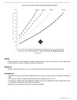
To be supplied by the System's Owner.
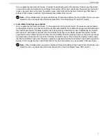
Provides an optional feature to the System Control Logic that works
in conjunction with the Automatic Fresh Water Flush option. When the Fresh Water Tank is empty, the switch
is open. As water rises in the tank, the switch closes, which informs the System Control Logic that there is
sufficient Fresh Water to perform the Automatic Fresh Water Flush Cycle.
Note:
When installed and connected to the Main Printed Circuit Board, the Fresh Water Tank Low Level
Switch must be connected as a Normally Open (NO), One Pole Single Throw (PST) switch.
2.
Fresh Water Tank High Level Switch
To be supplied by the System's Owner.
To be supplied by the System's Owner. Provides an optional feature
to the System Control Logic that shuts off the System automatically Fresh Water Tank High Level Switch when
the Fresh Water Tank is full (Note: System has to be operating in Automatic mode). Additionally, the System
will not start in Automatic mode when the Fresh Water Tank High Level Switch signals the System Control
Logic that the Fresh Water Tank is full. When the Fresh Water Tank is below the full mark, the switch is closed.
As water rises and reaches the top of the full mark, the switch opens. This informs the System Control Logic
that the Fresh Water Tank is full. If System operation is desired when the Fresh Water Tank Switch signals the
System Control Logic that the Fresh Water Tank is full, then the System may be operated in Manual mode.
Note:
When installed and connected to the Main Printed Circuit Board, the Fresh Water Tank High Level
Switch must be connected as a Normally Closed (NC), One Pole Single Throw (PST) switch.
27
System Description
Summary of Contents for Aqua Matic XL Series
Page 2: ......
Page 10: ......
Page 28: ......
Page 38: ......
Page 45: ...45 Commissioning...
Page 46: ......
Page 58: ......
Page 76: ......
Page 89: ...Chapter 10 Appendix 89...
Page 90: ...ABS Certificate of Design Assessment Aqua Matic XL 2200 3600 90...
Page 91: ...FCC Compliance 91 Appendix...
Page 92: ...DNV ISO 9001 Certificate Aqua Matic XL 2200 3600 92...
Page 93: ...Single Phase Electrical Motor Wiring 93 Appendix...
Page 94: ...Three Phase Electrical Motor Wiring Aqua Matic XL 2200 3600 94...
Page 95: ...Three Phase Transformer Wiring 95 Appendix...
Page 96: ...New System Initial Readings Form Aqua Matic XL 2200 3600 96...
Page 97: ...Daily System Readings 97 Appendix...
Page 98: ......
Page 99: ...Chapter 11 Exploded Parts Views 99...
Page 100: ...Exploded Parts View...
Page 103: ...7 8 9 10 11 12 13 14 15 16 17 20 19 18 21 22 23 24 25 26 1 2 3 4 5 6 Exploded Parts View 4...
Page 111: ...14 13 2 16 13 12 3 8 10 9 7 1 5 4 6 14 13 15 15 17 13 12 11 18 15 Exploded Parts View 12...
Page 113: ...19 16 2 21 16 14 3 9 11 10 8 1 5 4 6 12 22 20 18 16 17 15 15 13 7 Exploded Parts View 14...
Page 115: ...2 3 10 12 11 9 1 5 4 21 13 20 18 15 19 18 19 15 17 14 16 8 18 15 7 Exploded Parts View 16...
Page 117: ...10 26 11 9 5 5 4 20 1 7 18 3 2 16 13 15 12 14 13 23 24 21 24 25 Exploded Parts View 18...
Page 119: ...12 10 13 11 5 5 4 6 1 9 20 3 2 17 16 14 18 15 19 17 16 14 18 15 8 7 Exploded Parts View 20...
Page 128: ...6 7 2 3 2 5 10 10 12 1 11 8 9 8 11 6 7 4 2 13 14 29...
Page 138: ...Chapter 12 Electric Diagrams Foldouts 101...
Page 139: ...Aqua Matic XL Series Three Phase Wiring Diagram...
Page 140: ......
Page 141: ......


