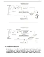
10. Record the System's performance readings in the daily log. Please utilize the form for
Daily System Readings
on page 97.
Startup Sequence
Before starting the System in Auto Mode, prepare yourself for the sequence of events below. After the System has
been started, the following process will occur:
1. Booster Pump electric motor will start.
2. Low Pressure Transducers will signal the System Control Logic, which will look for adequate feed water pressure
from the Booster Pump.
3. After 20 seconds, the High Pressure Pump electric motor will start and a screen will indicate that it has started.
4. Feed Water Flow Meter will signal the System Control Logic, which will look for adequate feed water flow through
the System.
5. After 20 seconds, the Automatic Back Pressure Regulator will rotate clockwise to build up operating pressure.
6. Product Water Flow Meter will register product water flow, as operating pressure exceeds the osmotic pressure
of the feed water. Product Water Flow will take priority to inform the control logic to increase or decrease
operating pressure in order to maintain the product water flow specification.
7. Salinity Probe will register the quality of the Product Water. When the salinity of the Product Water lowers to
the set point, the UV Sterilizer will energize (if installed).
8. The 3-Way Product Water Diversion Valve will energize, sending the Product Water to the Post-Filtration section.
This may take up to 30 minutes, as the Product Water flushes storage chemical from the System.
9. Feed Pressure, Feed Flow, Operating Pressure, Brine Flow, Product Flow and Product Salinity are all being
monitored and the values of these readings cause the System Control Logic to perform various tasks to maintain
proper functioning of the System.
10. The System may be manually stopped, or it may be programmed to stop at a given volume of Product Water
production.
11. When the System is signaled to perform a non-emergency stop, the Automatic Back Pressure Regulator Valve
will rotate counter-clockwise to lower operating pressure.
12. The 3-Way Product Water Diversion Valve will revert to non-potable water.
13. The UV Sterilizer will stop.
If the STOP is touched the System will immediately stop all functions. When the System is signaled to perform
a non-emergency stop:
a) The Automatic Back Pressure Regulator Valve will rotate counter clockwise to lower operating pressure.
b) The 3-Way Product Water Diversion Valve will revert to unpotable water.
c) The UV Sterilizer will stop.
d) The High Pressure Pump will stop.
e) The Booster Pump will stop.
f) If the System does not include the Automatic Fresh Water Flush option this ends the stop sequence.
g) If the System includes the Automatic Fresh Water Flush the Automatic Fresh Water Flush Valve will energize
to Fresh Water. After 7 to 15 minutes the Fresh Water Flush Valve will de-energize and the Stop sequence
is complete.
14. The System will go to a Fresh Water Flush Stand-by mode and count down the days until the next automatic
Fresh Water Flush Cycle. The Fresh Water Flush Cycle will automatically initiate until canceled or power is
disconnected from the System.
Powering the System OFF
Automatic Mode
Note:
Auto Mode is highly recommended for Operators and Owners.
Aqua Matic XL 2200 - 3600
50
Summary of Contents for Aqua Matic XL Series
Page 2: ......
Page 10: ......
Page 28: ......
Page 38: ......
Page 45: ...45 Commissioning...
Page 46: ......
Page 58: ......
Page 76: ......
Page 89: ...Chapter 10 Appendix 89...
Page 90: ...ABS Certificate of Design Assessment Aqua Matic XL 2200 3600 90...
Page 91: ...FCC Compliance 91 Appendix...
Page 92: ...DNV ISO 9001 Certificate Aqua Matic XL 2200 3600 92...
Page 93: ...Single Phase Electrical Motor Wiring 93 Appendix...
Page 94: ...Three Phase Electrical Motor Wiring Aqua Matic XL 2200 3600 94...
Page 95: ...Three Phase Transformer Wiring 95 Appendix...
Page 96: ...New System Initial Readings Form Aqua Matic XL 2200 3600 96...
Page 97: ...Daily System Readings 97 Appendix...
Page 98: ......
Page 99: ...Chapter 11 Exploded Parts Views 99...
Page 100: ...Exploded Parts View...
Page 103: ...7 8 9 10 11 12 13 14 15 16 17 20 19 18 21 22 23 24 25 26 1 2 3 4 5 6 Exploded Parts View 4...
Page 111: ...14 13 2 16 13 12 3 8 10 9 7 1 5 4 6 14 13 15 15 17 13 12 11 18 15 Exploded Parts View 12...
Page 113: ...19 16 2 21 16 14 3 9 11 10 8 1 5 4 6 12 22 20 18 16 17 15 15 13 7 Exploded Parts View 14...
Page 115: ...2 3 10 12 11 9 1 5 4 21 13 20 18 15 19 18 19 15 17 14 16 8 18 15 7 Exploded Parts View 16...
Page 117: ...10 26 11 9 5 5 4 20 1 7 18 3 2 16 13 15 12 14 13 23 24 21 24 25 Exploded Parts View 18...
Page 119: ...12 10 13 11 5 5 4 6 1 9 20 3 2 17 16 14 18 15 19 17 16 14 18 15 8 7 Exploded Parts View 20...
Page 128: ...6 7 2 3 2 5 10 10 12 1 11 8 9 8 11 6 7 4 2 13 14 29...
Page 138: ...Chapter 12 Electric Diagrams Foldouts 101...
Page 139: ...Aqua Matic XL Series Three Phase Wiring Diagram...
Page 140: ......
Page 141: ......


