Installer Minimum Qualifications
The System's Installer must have technical expertise in the following areas:
• Electrical, Electronic, Electric Motors and Circuits
• Electromechanical and Mechanical Systems
• Hydraulic and Liquid Pressure and Flow Systems
• Piping and Plumbing Systems
• Water Suction and Pressure Lines
• Thru-Hull Fitting below and above water level
Do not attempt maintenance and repair if you are not proficient in the aforementioned fields of expertise.
Warnings
Danger: ELECTRICAL SHOCK HAZARD
The Aqua Matic XL installation procedures expose the installer
to high voltage and potential electrical hazards. Technicians should only attempt installation if (1) they are
qualified electricians and (2) surrounding conditions are safe.
Caution:
Do not attempt Installation, commissioning, troubleshooting, or repair of the Aqua Matic XL unless
you are proficient in the fields/functions listed within the section
Installer Minimum Qualifications
on page 18.
Caution:
The RO Membrane Element is stored in sodium bisulfite. Avoid skin and eye contact with this
packaging solution. If skin contact occurs, rinse skin thoroughly with water. If eye contact occurs, flush eyes
repeatedly with water and notify a physician immediately.
Caution:
Never mount the liquid holding component above any electrical or electronic device. Extensive
damage to the electronic device will result if liquid enters device during maintenance and/or component failure.
Important:
Do not over-tighten PVC fittings. If threaded pipe fittings leak after installation, remove the fitting,
clean the mating threads, apply three (3) to four (4) wraps of Teflon tape to the male threads, apply liquid
Teflon pipe sealer sparingly, and thread the parts back together. PVC fittings should be hand tightened,
without the use of a wrench.
Important:
The Sea Cock Valve, Inline Pressure Gauge, Sea Strainer, Rinse Clean Inlet Valve, and Booster
Pump should be installed below water level. This will aid the Booster Pump in priming.
Important:
Always allow hoses and tubes to enter and exit straight from the connection
for a minimum of 1
in. prior to a bend
. If stress is placed on the fitting due to a tight bend, the fitting will leak and may break.
Important:
All connection lines should be as short and straight as possible using minimum fittings. Ensure
that they are not “kinked”.
Important:
The Electrical Control Touch Panel must be accessible for operation and monitoring of the system.
Important:
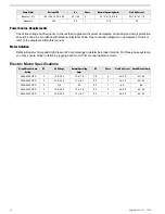
Ensure that the power source is sufficiently sized to provide the correct voltage and cycles during
System start up and operation.
Remember:
Install the system and its supporting components in an accessible manner.
Aqua Matic XL 2200 - 3600
18
Summary of Contents for Aqua Matic XL Series
Page 2: ......
Page 10: ......
Page 28: ......
Page 38: ......
Page 45: ...45 Commissioning...
Page 46: ......
Page 58: ......
Page 76: ......
Page 89: ...Chapter 10 Appendix 89...
Page 90: ...ABS Certificate of Design Assessment Aqua Matic XL 2200 3600 90...
Page 91: ...FCC Compliance 91 Appendix...
Page 92: ...DNV ISO 9001 Certificate Aqua Matic XL 2200 3600 92...
Page 93: ...Single Phase Electrical Motor Wiring 93 Appendix...
Page 94: ...Three Phase Electrical Motor Wiring Aqua Matic XL 2200 3600 94...
Page 95: ...Three Phase Transformer Wiring 95 Appendix...
Page 96: ...New System Initial Readings Form Aqua Matic XL 2200 3600 96...
Page 97: ...Daily System Readings 97 Appendix...
Page 98: ......
Page 99: ...Chapter 11 Exploded Parts Views 99...
Page 100: ...Exploded Parts View...
Page 103: ...7 8 9 10 11 12 13 14 15 16 17 20 19 18 21 22 23 24 25 26 1 2 3 4 5 6 Exploded Parts View 4...
Page 111: ...14 13 2 16 13 12 3 8 10 9 7 1 5 4 6 14 13 15 15 17 13 12 11 18 15 Exploded Parts View 12...
Page 113: ...19 16 2 21 16 14 3 9 11 10 8 1 5 4 6 12 22 20 18 16 17 15 15 13 7 Exploded Parts View 14...
Page 115: ...2 3 10 12 11 9 1 5 4 21 13 20 18 15 19 18 19 15 17 14 16 8 18 15 7 Exploded Parts View 16...
Page 117: ...10 26 11 9 5 5 4 20 1 7 18 3 2 16 13 15 12 14 13 23 24 21 24 25 Exploded Parts View 18...
Page 119: ...12 10 13 11 5 5 4 6 1 9 20 3 2 17 16 14 18 15 19 17 16 14 18 15 8 7 Exploded Parts View 20...
Page 128: ...6 7 2 3 2 5 10 10 12 1 11 8 9 8 11 6 7 4 2 13 14 29...
Page 138: ...Chapter 12 Electric Diagrams Foldouts 101...
Page 139: ...Aqua Matic XL Series Three Phase Wiring Diagram...
Page 140: ......
Page 141: ......

