b. Solution: Tighten any loose fitting or connection at the Inlet of the Booster Pump or prior to it that is allowing
air to enter the feed line. Replace worn or broken seal or O-ring at the Inlet of the Booster Pump or prior to
it that is allowing air to enter the feed line. Check positioning of all valves at or prior to the Inlet of the Booster
Pump that may be allowing air to enter the feed line.
Inlet Vacuum/Pressure Gauges
1.
Problem: A Vacuum/Pressure gauge needle does not move or does not register proper vacuum or
pressure.
a. Description: Vacuum/Pressure Gauges have a narrow orifice at the bottom of the pipe fitting end. This orifice
can become plugged with debris or corrosion.
b. Solution: Using a small diameter wire, clean the debris from the orifice.
Sea Strainer
1.
Problem: System feed water pressure is low and insufficient to keep the System in operation because
the O-Ringis not properly seated, is worn, or is not properly compressed allowing air to enter the Feed
Line.
a. Description: This section of the Feed Line is under a vacuum condition when the System is in operation. If
the Sea Strainer O-Ring is not properly seated, air will enter the feed line causing the System to loose
pressure. Look for air bubbles moving through the Sea Strainer and into the Feed Line.
b. Solution: Properly seat or replace the Sea Strainer O-Ring.
2.
Problem: System feed water pressure is low and insufficient to keep the System in operation because
the Sea Strainer mesh screen is blocking feed water flow.
a. Description: The Sea Strainer mesh screen element is the first line of defense to trap large suspended solids
entering the Feed Line. Depending on Feed Water conditions the screen may plug up rapidly. Marine growth,
plastic bags, jelly fish, and other debris can easily enter the feed line and plug up the Sea Strainer mesh
screen.
b. Solution: Regularly check and clean the Sea Strainer mesh screen. Keep it clear and free of debris.
Booster Pump
The Booster Pump is a centrifugal pump. When mounted at or below feed water level, it is able to draw the feed
water and deliver it with pressure into the pre-filtration components and High Pressure Pump. If mounted above
feed water level, the Booster Pump may have trouble priming when air enters the feed line. Prior to assuming that
the Booster Pump’s Electric Motor has failed, perform a Function Test as described in
Manual System Check
on
page 43.
1.
Problem: The Booster Pump leaks feed water between the pump and motor.
a. Description: The Booster Pump has a ceramic and carbon seal. Ceramic and carbon seals will weep if the
pump is not operated for extended periods of time. When used regularly, the seal will give approximately
2000 hours of use. The seal continually wears during use and must be replaced approximately every 2000
hours of use. If left unused for extended periods of time, seal replacement may be required sooner.
b. Solution: Replace seal.
T-Connector Pressure Pickup
1.
Problem: Low Pressure Transducer does not register pressure.
a. Description: The ¼ in. (5 mm) O.D. tube connecting the T-Connector to the Low Pressure Transducer
Manifold may become kinked or debris may block the tube.
79
Troubleshooting
Summary of Contents for Aqua Matic XL Series
Page 2: ......
Page 10: ......
Page 28: ......
Page 38: ......
Page 45: ...45 Commissioning...
Page 46: ......
Page 58: ......
Page 76: ......
Page 89: ...Chapter 10 Appendix 89...
Page 90: ...ABS Certificate of Design Assessment Aqua Matic XL 2200 3600 90...
Page 91: ...FCC Compliance 91 Appendix...
Page 92: ...DNV ISO 9001 Certificate Aqua Matic XL 2200 3600 92...
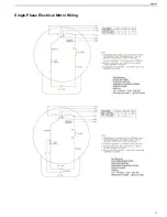
Page 93: ...Single Phase Electrical Motor Wiring 93 Appendix...
Page 94: ...Three Phase Electrical Motor Wiring Aqua Matic XL 2200 3600 94...
Page 95: ...Three Phase Transformer Wiring 95 Appendix...
Page 96: ...New System Initial Readings Form Aqua Matic XL 2200 3600 96...
Page 97: ...Daily System Readings 97 Appendix...
Page 98: ......
Page 99: ...Chapter 11 Exploded Parts Views 99...
Page 100: ...Exploded Parts View...
Page 103: ...7 8 9 10 11 12 13 14 15 16 17 20 19 18 21 22 23 24 25 26 1 2 3 4 5 6 Exploded Parts View 4...
Page 111: ...14 13 2 16 13 12 3 8 10 9 7 1 5 4 6 14 13 15 15 17 13 12 11 18 15 Exploded Parts View 12...
Page 113: ...19 16 2 21 16 14 3 9 11 10 8 1 5 4 6 12 22 20 18 16 17 15 15 13 7 Exploded Parts View 14...
Page 115: ...2 3 10 12 11 9 1 5 4 21 13 20 18 15 19 18 19 15 17 14 16 8 18 15 7 Exploded Parts View 16...
Page 117: ...10 26 11 9 5 5 4 20 1 7 18 3 2 16 13 15 12 14 13 23 24 21 24 25 Exploded Parts View 18...
Page 119: ...12 10 13 11 5 5 4 6 1 9 20 3 2 17 16 14 18 15 19 17 16 14 18 15 8 7 Exploded Parts View 20...
Page 128: ...6 7 2 3 2 5 10 10 12 1 11 8 9 8 11 6 7 4 2 13 14 29...
Page 138: ...Chapter 12 Electric Diagrams Foldouts 101...
Page 139: ...Aqua Matic XL Series Three Phase Wiring Diagram...
Page 140: ......
Page 141: ......


