Ice making section:
Remove from carton.
Remove all panels.
Utility Connection Route
:
Electrical: The unit is supplied with a power cord.
The power cord can be routed out the back, left
side or top. There is also an interconnecting control
wire that must be routed between the ice making
head and the CP unit. That wire can be routed out
the back or top.
Water Supply: The water supply can be routed
from the top, back or left side.
Drain: The drain can be routed out the back or the
left side.
Refrigeration Tubing: The tubing can be routed out
the top or the back.
Adapters:
In many cases an adapter kit will be required when
placing the head unit on a bin or dispenser. See
sales information for the correct kit. Place adapter
kit onto bin or dispenser top. If adapter does NOT
have gasket tape install tape such as Scotsman
part number 19-0503-04.
Attachment:
If the unit is a direct fit, place it on the bin. If the
unit is in a position that it need not be moved to
complete the installation, secure it to the bin with
the hardware provided with the head unit.
On some bins or dispensers it may be necessary
to drill small holes and use field supplied sheet
metal screws to secure the ice making head to that
bin, dispenser or adapter.
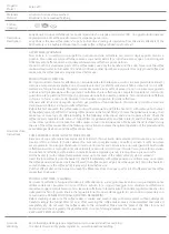
Control Wire
Plug the interconnecting control wire into the
harness at the back of the head unit’s electrical
box.
Eclipse
ä
1300, 1600
April 2003
Page 18
Ice Making Section Control Wire Connection
IMS Shown on Ice Dispenser
Control
Wire
Connector
Electrical Box in
Ice Making Head


