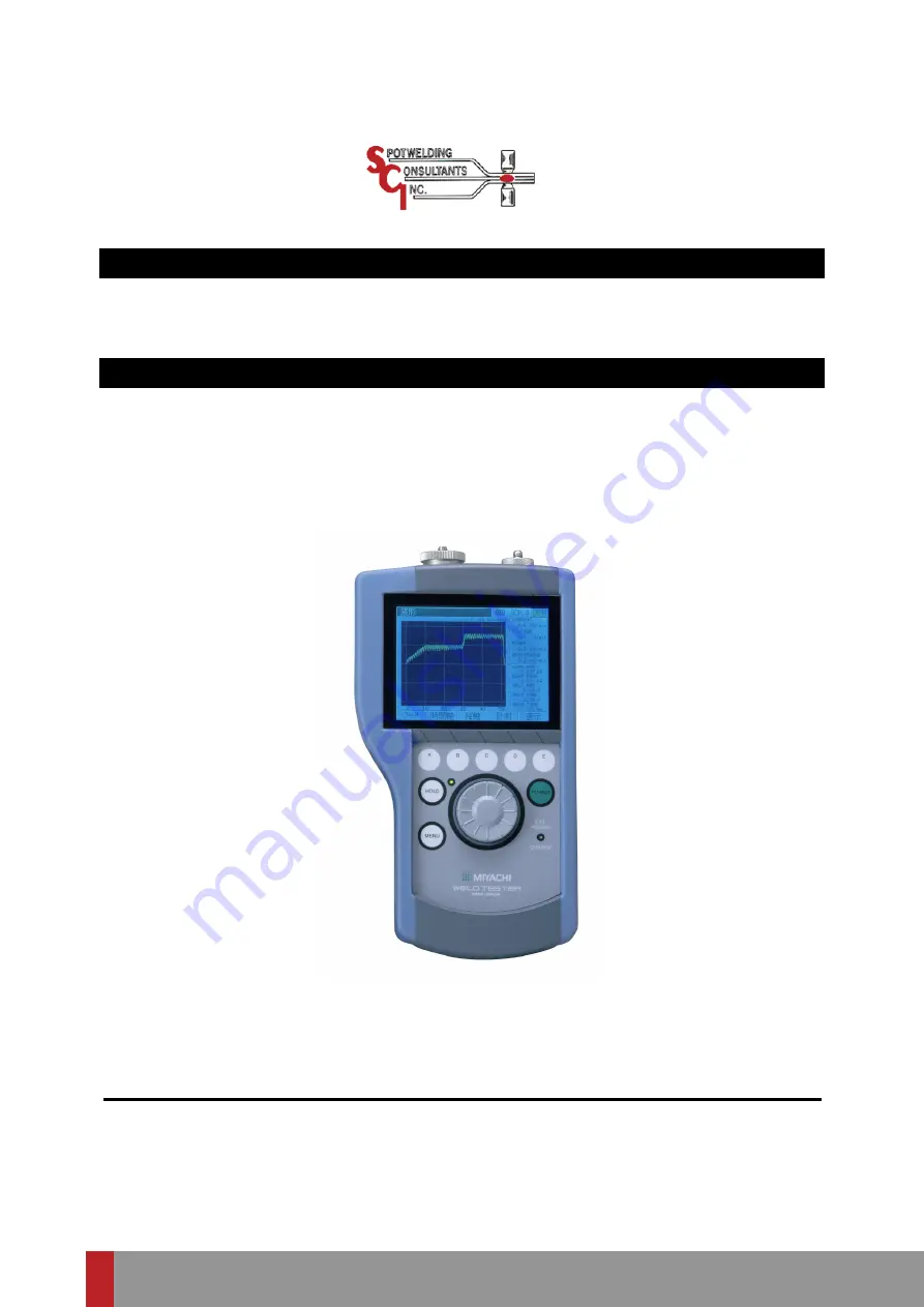
SCI MM-380A Operation Manual Download Page 1


WELD TESTER 

MM-380A 

OPERATION MANUAL 


Thank you for your purchase of the Miyachi Weld Tester 

MM-380A

Please  read  this  manual  carefully  to  ensure  correct  use.  Keep  the  manual 

handy after reading for future reference.


K05M0811E-02 

www.spotweldingconsultants.com

Summary of Contents for MM-380A

Page 1: ...N MANUAL Thank you for your purchase of the Miyachi Weld Tester MM 380A Please read this manual carefully to ensure correct use Keep the manual handy after reading for future reference K05M0811E 02 ww...

Page 2: ...sic Operation 7 1 1 Startup 7 1 2 Using the Encoder 7 2 a Selecting Menus 7 2 b Moving the Cursor and Changing Parameters 7 3 c Scrolling a Screen 7 4 3 Shutdown 7 5 8 Operation Screens 8 1 1 Operatio...

Page 3: ...ium Ion Battery 11 2 4 Replacing the Lithium Battery 11 2 12 Data Communication 12 1 1 Data Transfer 12 1 2 Configuration 12 1 3 Protocol 12 2 a Unidirectional communication mode unidirectional in the...

Page 4: ...Please read them all The hazard signs have the following meanings Mishandling may cause imminent risk of death or serious injury Mishandling may cause risk of death or serious injury Mishandling may c...

Page 5: ...e of damage Do not walk on twist or tug the cables Damaged cable may result in an electric shock short circuit or fire For repair or replacement contact your dealer or Miyachi Corporation In the event...

Page 6: ...all the way Dust or improper insertion may lead to the plug heat up and catch fire Hold the power plug when removing or inserting it Removing the power plug by pulling on the cable may damage the pow...

Page 7: ...nstable or weak Check the voltage and power frequency before installation Keep the exterior clean with a soft cloth or cloth lightly dampened with water For stains clean them off using a diluted neutr...

Page 8: ...e current and force waveforms Extensive display capability capabilities obviating the need for an oscilloscope Incorporates a zoom display function which permits the user to change the spacings of the...

Page 9: ...3 Packing List Check the contents of the package In the case of damaged or missing items please contact Miyachi Corporation 1 Accessories Item Item code Qty Strap PC021923 1 Operation manual EV000886...

Page 10: ...117 Voltage detection cord 42665 for attaching current force sensor EK000017 Force sensor MA 520 98 06N 10kgf max EG000112 Force sensor MA 521 980 6N 100kgf max EG000113 Force sensor MA 522 9806N 1 00...

Page 11: ...HOLD button ON Hold mode No Yes HOLD button OFF Hold mode canceled Yes No MENU button Shows the menu list on the display Display Shows measured values waveforms and operation screens Refer to Chapter...

Page 12: ...he encoder EXT POWER CHARGE lamp Lit when the MM 380A is connected to an external power supply and blinked when charged 2 Top Toroidal coil connector Plug a toroidal coil into this connector Multiconn...

Page 13: ...jack Connect the dedicated AC adapter here when charging the battery built into the MM 380A or using an external power supply CAUTION Connect only the dedicated AC adapter to the AC adapter jack Fail...

Page 14: ...nector to connect the instrument and PC with an optional RS 232C communication cable Used to transfer measured values and waveform data to the PC 5 Rear Battery cover A cover to protect the battery Th...

Page 15: ...easurement Current measurement Refer to 1 in Chapter 9 Voltage measurement Refer to 1 in Chapter 9 Force measurement Refer to 3 in Chapter 9 Refer to 3 in Chapter 7 Refer to Chapter 12 Connect measure...

Page 16: ...To charge the built in battery lithium battery or use an external power supply connect the power supply to the AC adapter jack on the right side of the MM 380A with the dedicated AC adapter 1 Plug the...

Page 17: ...oil suited to your operating environment The toroidal coils of the following sizes can be used Toroidal coil model Type MB 800K 1 sensitivity coil with 800mm bracket MB 400K 1 sensitivity coil with 40...

Page 18: ...circular form of the toroidal coil when fitting it CAUTION If the toroidal coil is fitted in reverse orientation the waveforms in the WAVEFORM screen and the analog output waveforms measured with the...

Page 19: ...onnect any device to the toroidal coil connector The MM 380A is calibrated one to one with the current force sensor Do not use any other sensors If you purchase a current force sensor later the sensor...

Page 20: ...a commercial force sensor and force sensor amplifier connected to the external 10 V voltage input Have ready a force sensor and force sensor amplifier purchased separately Follow the steps described...

Page 21: ...ce sensor and the force sensor amplifier CAUTION Before measuring the force be sure to set the force sensor s offset to 0 Note that you must at this time make sure that no force is applied to the sens...

Page 22: ...tion 1 Startup 1 To use an external power supply connect the power supply to the AC adapter jack with the dedicated AC adapter Refer to Chapter 6 1 2 Press the POWER button An operation screen appears...

Page 23: ...own Changing parameter setting Next Previous Scrolling screen Right or Down Left or Down You can confirm the selected menu or parameter by pressing the encoder a Selecting Menus 1 Press the MENU butto...

Page 24: ...or entry The parameter input field is selected turning its background blue 3 Turning the encoder clockwise or counterclockwise show the desired value When the parameter is numerical the value increase...

Page 25: ...een FORCE press operation button C Scrolling becomes enabled turning the SCRL key background to yellow 2 Turn the encoder clockwise or counterclockwise The screen scrolls down as you turn it clockwise...

Page 26: ...MM 380A 7 Basic Operation 7 5 3 Shutdown 1 Press the POWER button POWER button...

Page 27: ...itchover sequence through operation buttons A to E Menu list MEAUREMENT screen WAVEFORM screen ALL CYCLE screen WAVEFORM FORCE screen SETUP 1 screen SETUP 2 screen SETUP 3 screen A B A B WAVEFORM scre...

Page 28: ...asurement even while the screen is being updated following a measurement In contrast the WAVEFORM and ALL CYCLE screens accept next measurement only after the screen is updated If you perform the oper...

Page 29: ...cted in the VIEW screen Bottom Shows the measurement range for each measurement item in brackets 3 Measured values M VALUE Shows the measurement value of the each item Conditions SETUP Pressing operat...

Page 30: ...ent flow WELD TIME Shows the time from the detection of a current trigger to when the current flow is determined to be terminated CONDUCTION ANGLE Shows the maximum conduction angle within the current...

Page 31: ...EAK EXTERNAL VOLTAGE P EXT Shows the peak external input voltage converted at the preset conversion factor REAL TIME EXT R EXT 1 The MM 380A constantly measures the external 10 voltage while the hold...

Page 32: ...gs for the four waveforms shown on the grid 4 Measured values M VALUE Shows the measured values of five 5 items Measurement items can be selected in the VIEW screen FIT Pressing operation button A red...

Page 33: ...hows the measured values of five 5 items Measurement items can be selected in the VIEW screen Position MOVE Pressing operation button A makes it possible to move the waveforms In this condition turn t...

Page 34: ...n The function keys above operation buttons A to D show the item names for the displayed waveforms The displayed item names vary depending on the selection of waveform display items In the above scree...

Page 35: ...tion information Shows the current position information of the cursor You can move the white line cursor on the grid by turning the encoder clockwise or counterclockwise 5 Measured values M VALUE Show...

Page 36: ...be selected in the VIEW screen Force FORCE Pressing operation button A displays the ALL CYCLE screen Force Recalculate RECALC Pressing operation button B recalculates the measured current and voltage...

Page 37: ...culation interval 3 Measured value 1 Shows the measured values of five 5 items Measurement items can be selected in the VIEW screen Force CURR Pressing operation button A displays the ALL CYCLE screen...

Page 38: ...ion interval 2 Force Time FORCE 2 Time from when the force signal exceeds the force start level to when the signal reaches the force end level Force Start Time ELECTR CLOSE 1 Time from the force exter...

Page 39: ...oves the waveforms to the right or left Pressing operation button B again locks the waveforms 4 Function keys Spacing INTVL Pressing operation button C makes it possible to adjust the grid spacing on...

Page 40: ...and mode combinations When TRIGGER Current CURRENT is selected When TRIGGER Current CURRENT is selected force and external 10V voltage input are not measured MODE NORMAL Current normal mode The instr...

Page 41: ...f current upon input of a current signal after which it enters hold mode After displaying the data on screen the instrument goes into wait state until the next current signal is input The instrument s...

Page 42: ...surement only upon input of current or force or external 10V voltage input 1 When you have selected Auto for Trigger attach the force sensor The instrument performs a zero force adjustment when the ho...

Page 43: ...screen the instrument goes into wait state until the next force signal is input The instrument shows in the measured value field without showing the measured value and making any OK NG judgment on the...

Page 44: ...The instrument starts measurement each time a force signal is input making an OK NG judgment and showing the measured value and waveform To pass multiple current pulses refer to the PULSE MODE settin...

Page 45: ...ent time of external 10V voltage input upon input of this voltage After displaying the data on screen the instrument goes into wait state until the next external 10V voltage input signal is input The...

Page 46: ...oltage is measured at intervals of half a second In this trigger mode the instrument measures only External 10V voltage To use this trigger mode select REAL TIME ECTERNAL R EXT in the VIEW screen Pres...

Page 47: ...ect this option to measure AC output inverter welding current in units of cycle Set the frequency of the current you wish to pass in FREQUENCY in the SETUP 1 screen Measurement time 4 000 ms max 50 Hz...

Page 48: ...t intervals Measurement time 100 ms max When you have selected ms SHORT you cannot measure force external 10V voltage input or displacement Current range CURREN T RANGE Select from the following five...

Page 49: ...e Frequency CURRENT AC TIME CYC Hz Set the frequency of the current to be measured as follows according to the CURRENT and TIME combination M050 M053 M056 M059 M063 M067 M071 M077 M083 M091 M100 M111...

Page 50: ...Continued to next page Current may be passed several times in a single welding sequence Use the impulse settings to measure such a current The impulse settings are designed for current measurement Sel...

Page 51: ...measured Current trigger start Set the current flow interval to 500ms or less Force trigger start When external 10V voltage input and displacement are measured the instrument operates in the same mann...

Page 52: ...is selected for TIME at least 2ms of the interval is required If the number of measurement stages are less than the number of stages specified by PULSE No the instrument makes measurement for the max...

Page 53: ...strument starts measurement determining the point in time where the start current is exceeded as the measurement start point Measurement is possible only if the current at the second stage is larger t...

Page 54: ...s When CYC 50 60Hz CYC LONG or CYC Hz is selected for TIME 0 0 99 5CYC When ms is selected for TIME 0 99ms When ms SHORT is selected for TIME 0 0 9 9ms Current Fall Level CURR FALL LEVEL When DC is se...

Page 55: ...50 60Hz CYC LONG or CYC Hz is selected for TIME 0 5 9 5CYC When ms is selected for TIME 1 99ms When ms SHORT is selected for TIME 0 0 9 9ms Set a time so that currents of measurable magnitude shaded a...

Page 56: ...is selected for SELECT MEAS in the STATUS 1 screen set FORCE START TIME and FORCE END TIME in the range from 0 to 6 000 ms in units of 10 ms As for force there are two input fields for each item becau...

Page 57: ...FO RM Prints the waveforms of the five 4 items selected in the VIEW screen The vertical and horizontal scales applied to the printed waveforms are those set in the WAVEFORM screen You can select the w...

Page 58: ...Prints after the end of measurement 1 Parameter setting Condition Data Range SCHDUL E AREA Set the range of condition numbers to print condition data from 001 to 127 The setting of condition data rang...

Page 59: ...MM 380A 8 Operation Screens 8 33 Print example of COPY Print example of SCHEDULE Print example of HISTORY Print example of HISTORY...

Page 60: ...is fixed to RS 232C Communication Speed COMM SPEED Select from 9 600 bps 19 200 bps and 38 400 bps Select an item to output from the following To output first select an item then press the communicat...

Page 61: ...Overrange error or Pulsation error Current All Cycles CURR ALL CYCLE Outputs current all cycles Communication setting Continued from previous page Force All Cycles FORCE ALL CYCLE Outputs force all c...

Page 62: ...you have selected WAVE MEMORY for SAVE SELECT in the STATUS 3 screen the MM 380A is in mode to save measured values all cycles and waveforms Measured value data 5 selected measured values 100 Older da...

Page 63: ...red values showing the cursor that encloses the on screen history line by line You can move the cursor by turning the encoder clockwise or counterclockwise To save measured values all cycles and wavef...

Page 64: ...forms from the flash memory built into the MM 380A move the cursor to a desired measured value and press operation button E READ At this time SELECT does not scroll the screen Therefore scroll the scr...

Page 65: ...ntage of full scale When you have selected FORCE for SELECT MEAS select a force trigger level 2 0 to 99 9 When you have selected EXTERNAL for SELECT MEAS select an external trigger level 2 0 to 99 9 F...

Page 66: ...999 Force Decimal Point FORCE DECIMAL External Decimal Point EXT DECIMAL When you have selected rated setting MANUAL SET for FORCE SENSOR set a force or external decimal point as follows When FORCE is...

Page 67: ...1 to 12 and day 1 to 31 TIME Set the time in the format hour 0 to 23 and minutes 0 to 59 CONTRAST Set a display contrast 1 to 10 1 Parameter setting POWER OFF TIME Set the time 00 to 30 after which t...

Page 68: ...exceed 100 points Older waveform is deleted as the number of pieces of data exceeds 20 or as the maximum measurement time is surpassed On the other hand you can check waveform data on the screen displ...

Page 69: ...escription Force Meter Information FORCE INFO Shows the force meter model 1 Parameter setting Serial No SERIAL NO Shows the serial number of the force meter 2 Function keys Return PREV Pressing operat...

Page 70: ...For more information refer to 1 2 a in Chapter 6 2 Start the MM 380A For more information refer to 1 in Chapter 7 3 Press the HOLD button The MM 380A enters hold mode allowing you to manipulate the sc...

Page 71: ...items in the SETUP 1 screen For more information refer to 2 j in Chapter 8 Item Setting Current AC Time CYC 50 60 Hz Start Cycle S CYCLE End Cycle E CYCLE Referring to the figure shown below set the c...

Page 72: ...lding power supply frequency setting MM 380A frequency setting Welding power supply frequency setting MM 380A frequency setting 50 Hz M050 91 Hz M091 53 Hz M053 100 Hz M100 56 Hz M056 111 Hz M111 59 H...

Page 73: ...the current calculation end time also by CURR FALL LEVEL an item that sets the percentage relative to the current peak to stop the calculation in the SETUP 2 screen To set the CURR FALL LEVEL proceed...

Page 74: ...r to 2 j in Chapter 8 Item Setting Current DC Time ms SHORT Start Cycle S CYCLE End Cycle E CYCLE Set a calculation interval 8 Press the MENU button and using the encoder select MEASURE from the menu...

Page 75: ...starts the signal selected as trigger is input 14 When the trigger signal is input to the MM 380A measurement starts Confirm the measurement results on the MEASUREMENT and WAVEFORM screens You can als...

Page 76: ...Using the encoder select STATUS from the menu list The STATUS 1 screen appears 6 Set the following items in the STATUS 1 screen For more information refer to 2 r in Chapter 8 Item Setting Measurement...

Page 77: ...igger For more information refer to 2 j in Chapter 8 10 Press operation button A twice The SETUP 3 screen appears 11 Set the following items in the SETUP 3 screen Item Setting FORCE START TIME 1 to 2...

Page 78: ...the force end level FORCE TIME 15 To display the waveforms of the measured items set those items in Waveforms 1 to 4 For more information refer to 2 b in Chapter 8 16 As necessary switch to the SETUP...

Page 79: ...Name Function 1 EXT TRG1 Force trigger signal input terminal Connect a force signal solenoid valve signal to measure the force and current timings Supply a 24 V DC voltage input signal For more infor...

Page 80: ...for extended periods remove the battery or charge it once every two months 2 Battery Specification Operation time Approx 2 hrs with 1 battery Approx 4 hrs with 2 batteries Recharge warning display Cha...

Page 81: ...ears Follow the steps below to replace the battery CAUTION When replacing the battery leave the MM 380A connected to the power supply using the AC adapter Removing the battery with the MM 380A unconne...

Page 82: ...re that the battery s positive side faces up firmly push the new battery into the battery holder 7 Confirm that the battery is properly fitted in the holder 8 Reattach the battery cover 9 Fasten the b...

Page 83: ...ion System RS 232C Transfer rate Select one option in the COMMUNICATION screen 9600 19200 38400 bps Data format 1 start bit 8 data bits 1 stop bit even parity Character code ASCII Checksum data None C...

Page 84: ...nts a space When multiple measured values are transmitted the data is arranged as follows Ex Transmitting 5 measured values 01 0005 001 CR Header Data 1 Data 2 Data 3 Data 4 LF Data 5 End Item Length...

Page 85: ...e Judgment Table Judgment result 1 M Measured value 3 Varies depending on measurement item Value obtained from measurement 1 N Measurement item 4 2 fixed digits from 00 to 18 refer to the Measurement...

Page 86: ...D E F G 0000 0 0 02kA 0 0V 0 00kW 0 00N CR LF H I J K L 0000 5 0 02kA 0 0V 0 00kW 0 00N CR LF 0001 0 0 02kA 0 1V 0 00kW 0 00N CR LF 0001 5 0 00kA 0 1V 0 00kW 0 00N CR LF No output is produced if wave...

Page 87: ...pling time 6 fixed digit Sampling time 2 unit ms I Waveform 1 Varies depending on measurement item Measured value in each sampling time 1 J Waveform 2 Varies depending on measurement item Measured val...

Page 88: ...rom 00 to 31 Instrument specific ID B All cycles count 4 fixed digit Number of all cycles transmitted C Refer to 1 Measured values D Cycle time Varies depending on measurement time setting Cycle time...

Page 89: ...4 19 24 54 00 1 97kA 01 3 78kA 04 10 0CYC 11 0N 13 0ms CR LF 001 11 14 19 22 24 00 0kA 01 0kA 04 0CYC 11 58 53N 13 115ms CR LF Item Length Description A Instrument No 2 fixed digits from 00 to 31 Inst...

Page 90: ...own the MENU key a message Initializing Please wait a moment appears after which the memory is initialized resetting all settings back to factory settings Set the data you recorded again The memory wi...

Page 91: ...rrent detection circuit Turn off the power and on again If E07 startup sensitivity level error appears again the MM 380A needs repair Please contact Miyachi Corporation E08 Main battery low voltage er...

Page 92: ...00 0kA range 10 0 to 200 0kA Measurement time Current AC Time CYC 50 60Hz CYC Hz 0 5 to 200 0CYC 50Hz 0 5 to 240 0CYC 60Hz 0 5 to 1000 0CYC 250Hz Current AC Time ms 1 to 2000ms Current AC Time CYC LON...

Page 93: ...welding power supply 1 rdg 20dgt 6 00kA or 60 0kA range Single phase AC welding power supply transistor welding power supply 1 rdg 3dgt AC inverter welding power supply DC inverter welding power suppl...

Page 94: ...nt values from the following to display Current RMS Current PEAK Voltage RMS Voltage PEAK Conduction angle Power Resistance Weld time Force 1 AVE Force 2 AVE Force PEAK Force time External 10V voltage...

Page 95: ...voltage input normal mode External 10V voltage input single trace mode External 10V voltage input normal trace mode Auto trigger Force constant start mode External 10V voltage input constant start mod...

Page 96: ...en SETUP screens PRINT screen COMMUNICATION screen HISTORY screen DATA READ screen STATUS screens External data output RS 232C Conditions Number of conditions 127 Power supply Single phase 100 to 200V...

Page 97: ...alibration please send your toroidal coil and force sensor together with the MM 380A Depending on the operating environment the extent of deterioration varies from one MM 380A to another Therefore the...

Page 98: ...MM 380A 16 Appearance 16 1 16 Appearance Unit mm...

Reviews: