14
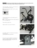
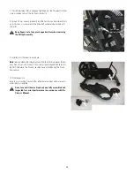
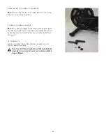
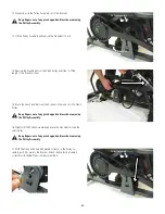
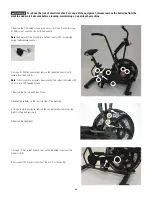
1. Remove the 3 indicated screws (with arrows) from the Crank Arm using
a 14 mm Socket Wrench and a 4 mm hex wrench.
Note:
Be aware that the Crank Arm and Pedal will fall if not supported
during the hardware removal.
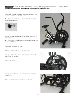
2. Using a #2 Phillips screwdriver, remove the indicated screws (with
circles) from the Shrouds.
Note:
To assist with re-assembly, be aware that the screws indicated with
an arrow are Self-Tapping Screws.
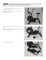
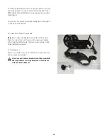
3. Remove the Shroud and Crank Cover.
4. Repeat procedures on the opposite side of the machine.
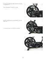
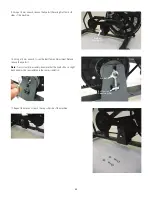
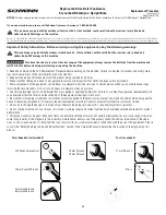
5. Inspect the Belts. The belts should barely be able to be pushed down-
ward at their mid-point.
[ Crank Belt (700-800N) and the Drive Belt (400N) ]
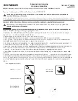
6. Using a 10 mm wrench, adjust the Belt Tension Adjustment Nuts on
both sides of the machine. Gradually turn it a 1/4 turn on each side.
Tighten (clockwise) the Adjustment Nuts to increase the belt tension,
loosen (counter-clockwise) to decrease.
To reduce the risk of electrical shock or usage of the equipment, always remove the batteries from the
machine and wait 5 minutes before cleaning, maintaining or repairing the machine.
Eye Bolt
Belt Tension
Adjustment Nut
Crank Belt
Drive Belt
Belt Tension
Adjustment Nut


