

58
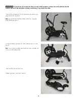
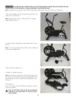
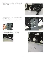
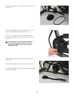
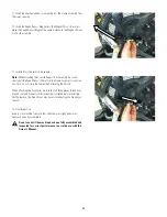
11. Insert the new Speed Sensor Assembly into the Frame Assembly from
the lower opening.
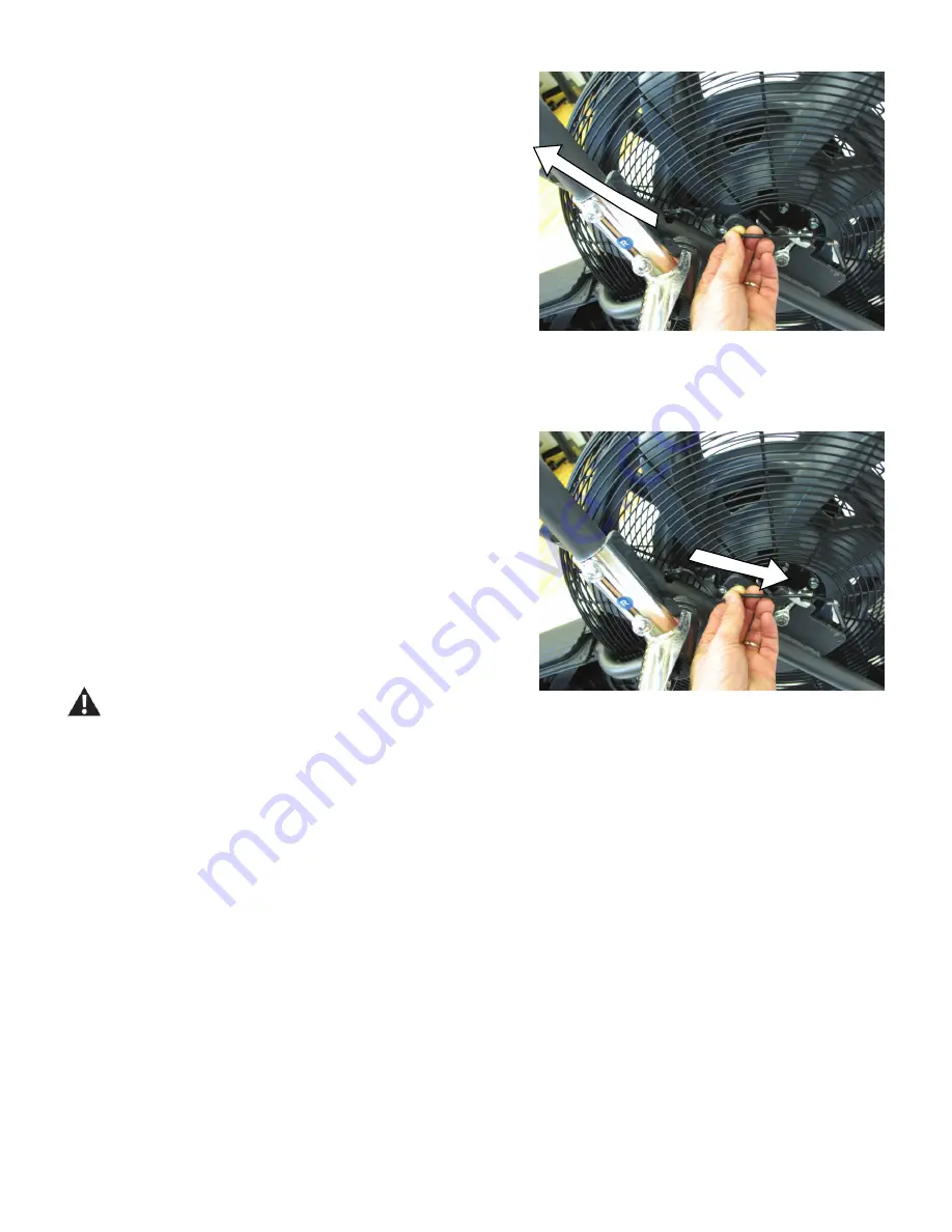
12. Insert the Speed Sensor Magnet into the Magnet Mount. Be sure to
place the Speed Sensor Magnet the same distance in the Magnet Mount
as the old assembly.
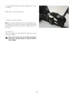
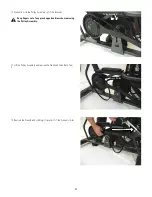
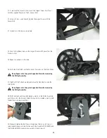
13. Installation is the reverse procedure.
Note:
When attaching the Console Support Bar Assembly, be sure to
slowly pull the Speed Sensor Cable from the Frame Assembly to remove
any slack. Do not crimp the Cable when attaching the Shroud.
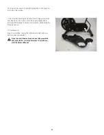
When attaching the Crank Arm, be sure that all three pieces (Crank Arm,
Crank Cover, and Connector Arm) are properly aligned before installing
ANY hardware. The Crank Cover may have rotated during the Crank Arm
removal.
14. Final Inspection
Inspect your machine to ensure that all hardware is tight and compo-
nents are properly assembled.
Do not use until the machine has been fully assembled and
inspected for correct performance in accordance with the
Owner’s Manual.


