


24
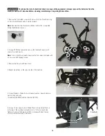
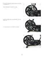
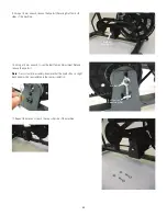
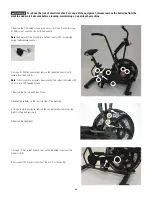
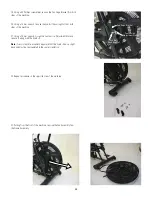
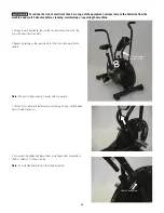
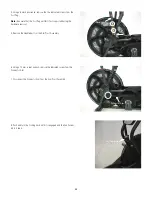
18. Gradually tighten the Belt Tension Adjustment Nuts by a full turn,
alternating between each side. Continue until the Crank Belt (700-
800N) and the Drive Belt (400N) can barely be pushed downward at
their mid-point.
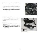
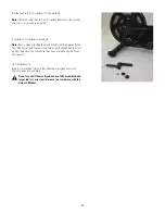
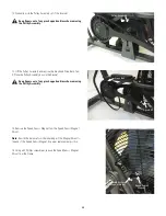
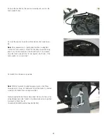
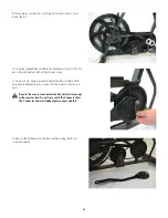
19. Using a 15 mm wrench, attach the Securing Nuts for the Eye Bolt
on both sides of the machine.
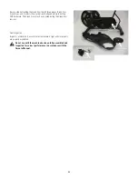
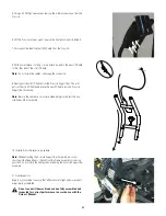
20. Installation is the reverse procedure.
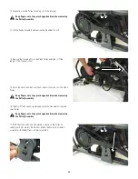
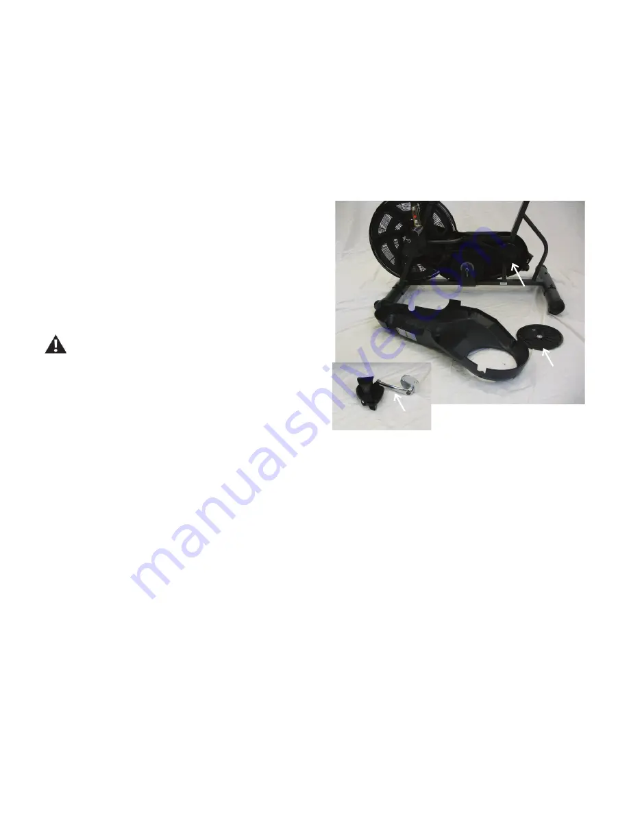
Note:
Be sure when attaching the Crank Arm that all three pieces
(Crank Arm, Crank Cover, and Connector Arm) are properly aligned
before installing ANY hardware. The Crank Cover may have rotated
during the Crank Arm removal.
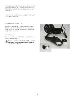
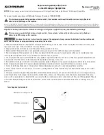
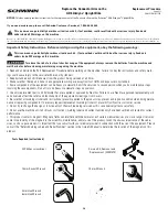
21. Final Inspection
Inspect your machine to ensure that all hardware is tight and compo-
nents are properly assembled.
Do not use until the machine has been fully assembled
and inspected for correct performance in accordance
with the Owner’s Manual.
Connector Arm
Crank Cover
Crank Arm


