


3.46
SEL-387-0, -5, -6 Relay
Instruction Manual
Date Code 20050919
Differential, Restricted Earth Fault, Thermal, and Overcurrent Elements
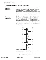
Thermal Element (SEL-387-6 Relay)
Cooling Stage 2 (or 3) (CSxyS)
Range: SEL
OGIC
control equation
The thermal element uses the output of SEL
OGIC
control equations to
determine which cooling stage is active, so that thermal element calculations
use the correct transformer constants. The settings XTYPE and NCS
determine the number of SEL
OGIC
control equations for which the relay will
prompt the user.
The Cs
xy
S SEL
OGIC
control equations can be set to any of the Relay Word
bits except rows 0 and 1 of
. However, it is critical that they be
configured to accurately indicate which cooling system is active. In the
simplest implementation, this will consist of one or two external contacts from
the monitored power transformer connected to optoisolated inputs on the
SEL-387 with the Cs
xy
S SEL
OGIC
control equations set to the corresponding
digital input.
Default Ambient Temperature (DTMP)
Range: –40 to 85°C, in 1°C steps
Select a reasonable value for DTMP, even if your data acquisition system
provides measurement of the ambient temperature (near the power
transformer). In this case the thermal element calculations will use the DTMP
setting, should the ambient temperature input not function on relay power up.
If your data acquisition system cannot measure ambient temperature, then the
thermal element calculations always use the DTMP value. The DTMP setting
units are degrees Celsius.
Transformer De-Energized (TRDE)
Transformer heating consists of heating resulting from transformer losses and
heating resulting from load. IEEE standard C57.91-1995 assumes the
transformer is energized and calculates an increase in oil and winding
temperatures resulting from transformer losses. Relay Word TRDE provides
the thermal element a way to distinguish between the de-energized and
energized stages. For example, wire a “52b” (normally closed) circuit breaker
auxiliary contact to input
IN101
and enter the SEL
OGIC
control equation TRDE
= IN101. When
IN101
asserts (circuit breaker main contacts open and the 52b
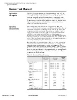
Table 3.2
Examples of Cooling Stages and MVA Ratings
XTYPE = 3
Cooling Stage
MVA Rating
CS1 (oil and air cooled)
MCS11 = 100
CS2 (forced air cooled)
MCS12 = 140
CS3 (forced oil and air cooled)
MCS13 = 170
XTYPE = 1
Cooling System
MVA Rating
Transformer 1
Transformer 2
Transformer 3
CS1 (oil and air cooled)
MCS11 = 100
MCS21 = 100
MCS31 = 100
CS2 (forced air cooled)
MCS12 = 140
MCS22 = 140
MCS32 = 140
CS3 (forced oil and air cooled)
MCS13 = 170
MCS23 = 170
MCS33 = 170
NOTE:
x designates the transformer
and y designates the cooling stage.
Summary of Contents for SEL-387-0
Page 10: ...This page intentionally left blank ...
Page 16: ...This page intentionally left blank ...
Page 56: ...This page intentionally left blank ...
Page 350: ...This page intentionally left blank ...
Page 388: ...This page intentionally left blank ...
Page 456: ...This page intentionally left blank ...
Page 494: ...This page intentionally left blank ...
Page 528: ...This page intentionally left blank ...


