background image

Vario F


7. 

Поиск


и устранение неисправностей


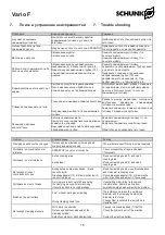
7.  Trouble shooting


Проблема


Возможная причина


Решение


Не удается заменить 

зажимающую головку


Недостаточно места между муфтой 

зажимающей головки и упором для 

заготовки.


Необходимо снять специальный упор для 

заготовки.


Эксцентричность детали 

превышает допуск


Нарушение соосности патрона SPANNTOP


Проверьте соосность в районе конуса и 

отрегулируйте ее при необходимости


Деталь вне допуска


Загрязнение муфты 


Загрязнение конуса


Снимите зажимающую головку (1) и 

очистите муфту


Снимите зажимающую головку (1) и 

очистите муфту


Рабочий ход слишком мал либо 

патрон не открывается


Загрязнение между направляющим 

механизмом (4) и корпусом патрона (2)


Переходник направляющей трубки (10) 

или направляющий механизм (4) вне 

допуска


Снимите зажимающую головку, 

переместите направляющую трубку назад 

и очистите паз в муфте.


Проверьте положение переходника 

направляющей трубки (10) или 

направляющего механизма (4). При 

необходимости 

– 

отрегулируйте его.


Форма заготовки отклоняется от 

нормы


Заготовка погнута во время зажатия. 

После механической обработки она 

должна вернуться к требуемой форме.


Используйте материал, менее склонный к 

потере формы. Иногда проблему можно 

решить

используя узкую, точечную 

зажимающую головку


Следы на поверхности детали


Точечное или линейное зажатие заготовки


Неправильный выбор типа зажимающей 

головки


Разность  между  диаметром  заготовки  и 

внутренним 

диаметром 

зажимающей 

головки слишком велика


Замените зажимную головку с насечкой на 

головку с гладким отверстием


Зажимное давление 

недостаточно


Заготовка слишком мала


Недостаточное гидравлическое давление 

зажимного цилиндра


Неисправен цилиндр либо заблокирована 

направляющая трубка


Замените зажимающую головку (1) на 

подходящую

Замените гидравлический блок станка


Обратитесь к производителю станка


Problem


Possible cause


Solution


Clamping head cannot be changed


Not enough room between clamping head 
coupling and workpiece stop


The work piece-specific stop must be reworked


Workpiece is eccentrically out of 
tolerance


SPANNTOP chuck is not concentric


Check concentricity at taper and adjust, 
if necessary


Workpiece is out of tolerance


Soiled coupling area 

Soiled taper


Remove clamping head (1) and clean 
coupling area


Remove clamping head (1) and clean 
coupling area


Not enough stroke or 
chuck does not open


Soiling between draw mechanism (4) and 
chuck body (2)


Drawtube adapter (10) or draw mechanism (4) 
is out of tolerance


Remove clamping head, move drawtube back 
and clean slot in coupling area


Check drawtube adapter (10) or draw mecha- 
nism (4) position and adjust it, if necessary


Workpiece bent out of shape


A work piece is bent out of shape during 
the clamping process. After machining, 
it should go back to its original shape


Use starting material that is less prone 
to deformation. Sometimes a narrow,


pointed clamping head will rectify the problem


Marks on the part surface


Point or linear work piece clamping


Wrong clamping head type


The  difference  between  the  workpiece 
diameter and the clamping head inside 
diameter is too large


Change from a serrated to a smooth bore 
clamping head


Not enough clamping pressure


Work piece is undersize


Not enough hydraulic pressure at the 
clamping cylinder


Defective cylinder or blocked drawtube


Change to a clamping head (1) that fits 
Check the hydraulic unit of the machine


Contact the machine builder


15


Summary of Contents for Vario F 100

Page 1: ...1 905 712 2210 info ca schunk com www ca schunk com SCHUNKPrecisionMachinery 86 571 8672 1000 86 571 8673 8800 info cn schunk com www cn schunk com SCHUNKIntecs r o 420 545229095 420 545220508 info c...

Page 2: ...c Safety Notes 9 3 Scope of Delivery 9 4 Product Description 10 5 Assembly 11 5 1 Mounting the segmented mandrel on the power chuck 11 5 2 Changing the segmented clamping sleeve 11 5 3 Changing the En...

Page 3: ...to observe the current safety regulations and legal prerequisites to avoid damage to persons and to the product during maintenance and repair work Before carrying out repairs personnel must have read...

Page 4: ...being in charge with tasks of the collet chuck must have read the relevant documentation before setting to work and in particular being familiar himself with the chapter dealing with Safety This is pa...

Page 5: ...ned according to the respective standards that apply and or the most up to date scientific and technological data e g VDI 3106 Principles The collet chuck complies with the specific safety regulations...

Page 6: ...tective windows because this may cause a threat to the life and limb of the operator in the case of a fracture in the chuck jaws Please observe all appropriate safety measures during the transportatio...

Page 7: ...y be carried out by reliable personnel the legal minimum age must be obser ved Only employ personnel on the collet chuck which has been trained and shown how to operate the mandrel Make use of the man...

Page 8: ...g device the machine must be equipped with a speed limiting device If the clamping device is changed it is important to adjust the stroke control to suit the new situation The centrifugal force of the...

Page 9: ...of the machi ne can cause injury Do not use solvents containing ester or polar solvents for cleaning the Vario F Seals and segmented clamping slee ves could otherwise be damaged The collet chuck is b...

Page 10: ...addition the entire clamping device is stiffened this has a positive effect on the service life of the tools The Vario F is a collet chuck which must be integrated into a ROTA THW vario 215 62 only Th...

Page 11: ...om the chuck and insert protective jaws Item 82 up to the max position marking on the chuck face The chuck mechanism is opened when chan ging the center sleeve or the Vario component When doing this e...

Page 12: ...dial indicator should be applied inside the taper and the spindle should be turned The clamping taper can be aligned if the concentricity error exceeds 0 01 mm Loosen the 6 screws M 10 in the face sid...

Page 13: ...hand Removing the SPANNTOP Clamping Head The removing of the Clamping Head is only possible when the chuck is in the changing position front position Attach the Changing Fixture see the separate parag...

Page 14: ...nd chuck body Item 1 from the mount Item 2 Remove pull mechanism Item 3 from the mount Item 2 Expand the fastening taper and pull down over the mount Item 2 Disassembling the chuck is carried out in r...

Page 15: ...ove drawtube back and clean slot in coupling area Check drawtube adapter 10 or draw mecha nism 4 position and adjust it if necessary Workpiece bent out of shape A work piece is bent out of shape durin...

Page 16: ...ews 3 11 Fastening screws 6 12 Fastening screws 6 13 Seal 1 14 Seal 1 9 9 1 HSW Vario F HSW HSW Vario F 0 3 9 Accessories 9 1 HSW clamping heads for in house machining to the required size For precisi...

Page 17: ...g Loading ring for boring to the required size Plug for boring to the required size Serrated bore style Smooth bore Inhouse machining 65 15 6000 45 000 105 000 3 58 SK 65 BZI 9 53 SK 65 BZIG 4 53 SK 6...

Page 18: ...QQ Type MQQ 2 PP PPG 100 160 2 2 Pneumatic change over Type PP is a pneumatic changing fixture A comfortable handle and an integrated valve make handling very easy The pneumatic clamping fixture type...

Page 19: ...ng length should be equivalent to at least 6 mm HSW 80 BZI clamping head Standard bores 20 mm 30 mm 40 mm 60 mm for self boring face side and soft bore The clamping length should be equivalent to at l...

Page 20: ......

Reviews: