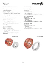
Vario F
Размер
Зажимной диапазон
оправки
Зажимной диапазон
многосегментной
зажимной втулки
65
от Ø4 до Ø65
с шагом 1 мм
±0,5
80
от Ø5 до Ø80
с шагом 1 мм
±0,5
100
от Ø16 до Ø100
с шагом 1 мм
±1
Size
Mandrel clamping
range
Clamping range of the
segmented clamping
sleeve
65
from Ø 4 to Ø 65
1 mm increments
± 0.5
80
from Ø 5 to Ø 80
1 mm increments
± 0.5
100
from Ø 16 to Ø 100
1 mm increments
± 1
3.
Комплект поставки
Цанговый патрон
(без зажимающей головки)
Винты
4.
Описание изделия
Цанговый патрон специально предназначен для крепления
деталей, при обработке которых предъявляются повышенные
требования к биению.
Патрон Vario F может использоваться в качестве заднего упора
при обработке в патроне.
В состав зажимающей головки входят вулканизированные
сегменты из упрочненной стали. Ее особенностями являются
«параллельное зажатие заготовки», исключительная точность
при минимальной деформации заготовки, низкие затраты
времени на подготовку к работе. Если патрон Vario F
используется в качестве патрона
с задним упором, последний
ввинчивается в этот патрон.
Инструмент плотно прижимается к неподвижному заднему
упору за счет деталей, обеспечивающих осевое натяжение,
действующее при зажимании заготовки. Это обеспечивает
исключительную стабильность крепления
заготовки, даже при
небольшой длине закрепляемой части детали. Кроме того, все
зажимное
устройство
оказывается
затянутым,
что
положительно влияет на срок службы инструмента.
Патрон Vario F может использоваться только совместно с
патроном ROTA THW vario 21
5-62.
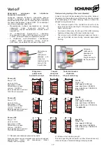
Патрон Vario F привинчивается к торцевой поверхности
патрона и приводится в действие при помощи специального
переходника. При этом защитные кулачки (поз. 82, раздел 5.1)
перемещаются внутрь патрона.
Одновременное крепление детали при помощи штатного и
цангового патронов невозможно, так как независимое развитие
этими устройствами зажимного усилия не предусмотрено.
Благодаря конструктивным особенностям стандартной
модификации патрона Vario F переключать на него регулятор
рабочего хода не требуется.
При отсутствии заготовки осуществляется калибровка крайних
положений патрона. Поскольку рабочий ход цангового патрона
меньше, чем у штатного, при этом выполняется холостое
перемещение, в ходе которого цанговый патрон полностью
сжимается и разжимается.
Если
регулятор
расхода
позволяет
устанавливать
зажимающий цилиндр в промежуточные положения, патрон
Vario F может использоваться вместе со специальным
удлинителем, что обеспечивает дополнительную оптимизацию
рабочего хода. Конструкция штатного патрона при этом не
изменяется.
Важно:
При переводе технологического процесса на работу с
цанговым патроном необходимо откорректировать
применяемые уровни рабочего давления в штатном и
цанговом патронах.
3.
Scope of Delivery
Collet chuck
(without clamping head)
Screws
4.
Product Description
The collet chucks are especially suited for clamping applica-
tions that require high run-out accuracies.
The Vario F chuck can be used as a back stop chuck for
chuck work.
The clamping heads consist of vulcanised, hardened steel
segments. They are characterised by “parallel workpiece
clamping”, extreme precision with minimal workpiece defor-
mation and rapid set-up times. A workpiece stop is screwed
into the chuck when the Vario F is used as a back stop chuck.
The tool is pulled firmly onto the fixed back stop by the axial
tensile components which take effect during clamping. This
allows for extremely stable clamping of the workpiece – even
with short clamping lengths. In addition, the entire clamping
device is stiffened – this has a positive effect on the service
life of the tools.
The Vario F is a collet chuck which must be integrated
into a ROTA THW vario 215-62 only.
The Vario F is screwed onto the face side of the power chuck
and is actuated via a special adapter. During this, the protec-
tive jaws (Item 82 – see chapter 5.1.) move inside the power
chuck.
Simultaneous workpiece clamping with the power chuck and
the collet chuck is not possible, since independent clamping
force introduction is not provided for.
The standard version of the Vario F is designed so that the
stroke control does not need to be switched over to the Vario.
If no workpiece is being clamped, the end positions of the
power chuck are queried. As the Vario F does not require the
same actuating stroke, a defined idle stroke is travelled via
the relocating sleeve for clamping and unclamping.
If an intermediate position can be programmed on the stroke
control in the clamping cylinder, a special extension to the
Vario F could allow for further optimised actuating travels. The
design of the power chuck remains unaffected.
Important:
The actuating pressure for the power chuck and the
collet chuck must be adjusted when converting the
clamping
task.
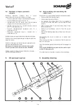
Размеры патронов Vario F
Sizes Vario F
10
Summary of Contents for Vario F 100
Page 20: ......


