background image

Vario F


Тип


Макс. усилие


Vario F 65 / Vario F 65-51


45 кН


Vario F   80


50 кН


Vario F 100


50 кН


Type


Max. actuating force


Vario F 65 / Vario F 65-51


45 kN


Vario F   80


50 kN


Vario F 100


50 kN


Снятие патрона Vario F


Снятие  оправки  из  патрона  осуществляется  в 

порядке, обратном порядку ее установки.


После  чистки  и  смазки  рекомендуется  поместить 

оправку на хранение в закрытый ящик.


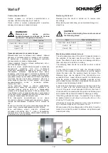
Removing the Vario F


Removal  from  the  chuck  is  carried  out  in  reverse  order 
accordingly.


After cleaning and lubricating, we recommend storage in a 
closed box.


ВНИМАНИЕ:


Максимальное 

осевое 

усилие, 

воздействующее  на  оправку,  не  должно 

превышать следующие значения.


CAUTION:


The max. axial actuating force must not exceed 
the following values.


Проверка радиального и осевого биения


Максимальная точность патрона Vario


F зависит, главным 

образом, от состояния конуса и переднего торца патрона. 

В  дополнение  к  загрязнению  необходимо  учитывать 

влияние износа, старения и повреждений.


Перед  проверкой  точности  патрона  необходимо  снять  с 

него зажимающую головку.


Кроме  того,  может  потребоваться  выровнять  основание 

зажимающего  устройства.  Для  этого  необходимо 

установить  циферблатный  индикатор  внутрь  конуса  и 

поворачивать  шпиндель.  Зажимающий  конус  можно 

выровнять, если отклонение от соосности превышает 0,01 

мм. Ослабьте 6 винтов M10 на торцевой стороне патрона, 

удерживая шпиндель в неподвижном состоянии, добейтесь 

отсутствия  биения  при  помощи  резинового  молотка,  а 

затем  вновь  затяните  винты  (крест

-

накрест,  при  помощи 

динамометрического  ключа,  с  моментом  затяжки, 

указанным в табл. 1

).


Чтобы  проверить  биение  в  осевом  направлении, 

циферблатный  индикатор  необходимо  установить  на 

торцевой  стороне  патрона  Vario  F  и  поворачивать 

шпиндель. Если биение превышает 0,005 мм, патрон Vario 

F необходимо снять, удерживая шпиндель в неподвижном 

состоянии, а затем проверить все контактные поверхности 

на предмет повреждения либо загрязнения.


Если  поверхности  приспособления  чисты,  можно 

попытаться  добиться  оптимального  радиального  биения, 

каждый  раз  поворачивая  устройство  Vario  в  патроне  на 

120°.


Если это не помогает, получить нужное радиальное биение 

можно только улучшив выравнивание самого патрона.


Если  необходимо,  можно  отметить  установочное 

положение  устройства  Vario  F,  чтобы  в  дальнейшем, 

помещая его в то же положение, обеспечивать повторение 

оптимальной точности крепления.


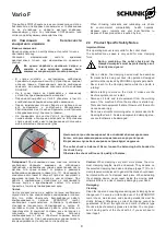
Monitoring radial and axial run-out


The  achievable  accuracy  of  the  Vario F  depends  mainly  on 
the  condition  of  the  taper  and  the  end  face  in  the  power 
chuck. The effects of wear and tear and damage should be 
taken into account in addition to soiling.


The  clamping  head  should  be  removed  in  order  to  check 
precision.


It  may  also  be  necessary  to  align  the  clamping  device 
mount.For  this  purpose,  a  dial  indicator  should  be  applied 
inside  the  taper  and  the  spindle  should  be  turned.  The 
clamping  taper  can  be  aligned  if  the  concentricity  error 
exceeds 0.01 mm. Loosen the 6 screws M 10 in the face side 
while  the  spindle  is  stationary,  establish  a  precise  run-out 
with a rubber hammer and then cross-tighten the screws with 
a torque wrench according to table 1.


A dial indicator should be positioned on the face side of the 
Vario  F chuck  and  the  spindle turned to check for axial 
run-out.  If  the  axial  run-out  exceeds  0.005  mm,  the  Vario  F 
chuck should be removed while the spindle is stationary and 
all contact surfaces should checked for damage or soling.


If the fitting surfaces are clean, it is possible to try to obtain 
an  optimal  radial  run-out  value  by  turning  the  Vario  on  the 
chuck by 120° each time.


If this does not work, the radial run-out can only be achieved 
by an improved alignment of the power chuck.


Where required, the mounting position of the Vario F must be 
marked  on  a  specific  position  to  achieve  an  optimal  repeat 
clamping accuracy.


12


Summary of Contents for Vario F 100

Page 1: ...1 905 712 2210 info ca schunk com www ca schunk com SCHUNKPrecisionMachinery 86 571 8672 1000 86 571 8673 8800 info cn schunk com www cn schunk com SCHUNKIntecs r o 420 545229095 420 545220508 info c...

Page 2: ...c Safety Notes 9 3 Scope of Delivery 9 4 Product Description 10 5 Assembly 11 5 1 Mounting the segmented mandrel on the power chuck 11 5 2 Changing the segmented clamping sleeve 11 5 3 Changing the En...

Page 3: ...to observe the current safety regulations and legal prerequisites to avoid damage to persons and to the product during maintenance and repair work Before carrying out repairs personnel must have read...

Page 4: ...being in charge with tasks of the collet chuck must have read the relevant documentation before setting to work and in particular being familiar himself with the chapter dealing with Safety This is pa...

Page 5: ...ned according to the respective standards that apply and or the most up to date scientific and technological data e g VDI 3106 Principles The collet chuck complies with the specific safety regulations...

Page 6: ...tective windows because this may cause a threat to the life and limb of the operator in the case of a fracture in the chuck jaws Please observe all appropriate safety measures during the transportatio...

Page 7: ...y be carried out by reliable personnel the legal minimum age must be obser ved Only employ personnel on the collet chuck which has been trained and shown how to operate the mandrel Make use of the man...

Page 8: ...g device the machine must be equipped with a speed limiting device If the clamping device is changed it is important to adjust the stroke control to suit the new situation The centrifugal force of the...

Page 9: ...of the machi ne can cause injury Do not use solvents containing ester or polar solvents for cleaning the Vario F Seals and segmented clamping slee ves could otherwise be damaged The collet chuck is b...

Page 10: ...addition the entire clamping device is stiffened this has a positive effect on the service life of the tools The Vario F is a collet chuck which must be integrated into a ROTA THW vario 215 62 only Th...

Page 11: ...om the chuck and insert protective jaws Item 82 up to the max position marking on the chuck face The chuck mechanism is opened when chan ging the center sleeve or the Vario component When doing this e...

Page 12: ...dial indicator should be applied inside the taper and the spindle should be turned The clamping taper can be aligned if the concentricity error exceeds 0 01 mm Loosen the 6 screws M 10 in the face sid...

Page 13: ...hand Removing the SPANNTOP Clamping Head The removing of the Clamping Head is only possible when the chuck is in the changing position front position Attach the Changing Fixture see the separate parag...

Page 14: ...nd chuck body Item 1 from the mount Item 2 Remove pull mechanism Item 3 from the mount Item 2 Expand the fastening taper and pull down over the mount Item 2 Disassembling the chuck is carried out in r...

Page 15: ...ove drawtube back and clean slot in coupling area Check drawtube adapter 10 or draw mecha nism 4 position and adjust it if necessary Workpiece bent out of shape A work piece is bent out of shape durin...

Page 16: ...ews 3 11 Fastening screws 6 12 Fastening screws 6 13 Seal 1 14 Seal 1 9 9 1 HSW Vario F HSW HSW Vario F 0 3 9 Accessories 9 1 HSW clamping heads for in house machining to the required size For precisi...

Page 17: ...g Loading ring for boring to the required size Plug for boring to the required size Serrated bore style Smooth bore Inhouse machining 65 15 6000 45 000 105 000 3 58 SK 65 BZI 9 53 SK 65 BZIG 4 53 SK 6...

Page 18: ...QQ Type MQQ 2 PP PPG 100 160 2 2 Pneumatic change over Type PP is a pneumatic changing fixture A comfortable handle and an integrated valve make handling very easy The pneumatic clamping fixture type...

Page 19: ...ng length should be equivalent to at least 6 mm HSW 80 BZI clamping head Standard bores 20 mm 30 mm 40 mm 60 mm for self boring face side and soft bore The clamping length should be equivalent to at l...

Page 20: ......

Reviews: