background image


Copyright © 2020 Axxiom Manufacturing, Inc.                                           47 


8.5.2.  Fan shroud, Fan, Fan Guard, and Motor 

Inspect weekly: Dirt and grease should be removed from these parts. Rusty or corroded 
surfaces should be sanded clean and repainted. Replace any component that is damaged or 
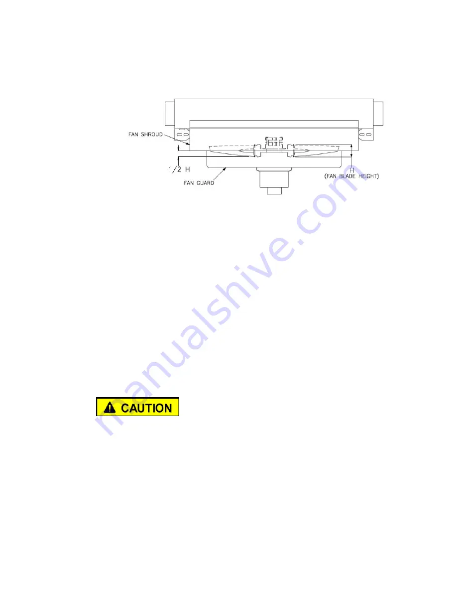
corroded. Install fan blade assembly as shown in Figure 8.1. 


Note:

 A corroded fan shroud allows fan air flow to escape resulting in cooling reduction. 

Damaged fan guard may not protect personnel from contact with moving parts.  


Figure 8.1 – Fan Blade Assembly 


8.5.3.  Internal Cleaning: 

Once a year disconnect piping and circulate a degreasing agent through 

the unit to remove sludge from the internal tubes. This will return the unit to full operating 
capacity. A thorough cleaning of the entire system in the same manner is desirable to avoid 
carry-over from unclean piping. The pre-filter (#1), after-filter (#2), air motor (#5), air filter 
(#14), air regulator (#14), and air lubricator (#15) should all be removed and serviced 
following this cleaning operation.


8.5.4.  Air Motor Air Supply Filter/Regulator: 

Once a day completely open the filter/regulator 

petcock drain to purge moisture and debris. The aftercooler fan speed can be controlled by 
changing the supply air pressure. Confirm that the air motor pressure does not exceed the 
specified maximum pressure (see Section 11.0, Table 2). 

 
8.5.5.  Air Motor Lubricator: 

Once a day fill the air lubricator reservoir (#15) with oil. The air 

motor manufacturer recommends a detergent SAE #10 automotive engine oil or GAST 
AD220 oil; however, SAE 10W-30 may be substituted. Adjust the oil-fog lubricator (#15) 
to the proper flow rate (see note below). The lubricator flow rate is adjusted based upon the 
air cfm flow rate required for the air motor.  Refer to Section 11.0, Table 2 for air flow and 
drip rate requirement. Turn the socket head screw on top of the lubricator to adjust flow 
(clockwise to increase flow, counterclockwise to decrease flow). 


Failure to properly lubricate the air motor as detailed above will result in costly motor 
failure. 


Note:

 Two types of lubricators have been used in Schmidt® AirPrep Systems. Current 

production units are equipped with “oil-fog” lubricators (Style MP). Systems manufactured 
prior to September 2016 are equipped with “micro-fog” lubricators (Style L74M). Micro-
fog lubricator drip rates are significantly higher because only a fraction of the drip total 
enters the air stream. 


Filter/regulator and lubricator arrangement may vary from what is shown in the drawings 
included in this manual. Verify the type lubricator then adjust the drip rate accordingly.


8.5.6.


Air Motor

:

 If the motor is sluggish or inefficient, disconnect the air line and muffler (#17), 

and then add several teaspoons of solvent directly into the motor. Rotate the motor shaft by 
hand in both directions for a few minutes. Reconnect the air line and slowly apply air 
pressure until there is no trace of solvent in the exhaust air. Re-lubricate the air motor with 
a squirt of oil in the chamber. Reassemble and return to service. 

Summary of Contents for ACS 1200

Page 1: ...TO ALL USERS OF THIS EQUIPMENT Manual Part Number 7200 260 rev10 20 Available for downloading from SchmidtAbrasiveBlasting com Copyright 2020 AXXIOM Manufacturing Inc 11927 S Highway 6 Fresno Texas 77545 800 231 2085 281 431 0581 fax 281 431 1717 Website Visit us at www SchmidtAbrasiveBlasting com Manual ...

Page 2: ...blaster vessel before loading abrasive or performing any maintenance 6 Do Not use abrasives containing free silica Silica can cause silicosis or other related respiratory damage All operators must wear personal protective equipment for all abrasive blasting operations Observe all applicable local state and federal safety regulations in conjunction with airline filters and respiratory protection Re...

Page 3: ...ay result in minor or moderate injury It may also be used to alert against unsafe practices that may cause property damage WHITE LETTERS with BLUE BACKGROUND NOTICE Indicates that equipment could malfunction or potentially become damaged if certain instructions are not followed This manual contains terms that may be specific to the abrasive blast industry Understanding these terms will help you un...

Page 4: ... will cause serious injury or death Depressurize vessel prior to performing any maintenance See Section 6 2 4B 2 7031 007B Danger Pressurized Vessel Propelled objects will cause serious injury or death Depressurize vessel prior to performing any maintenance See Section 6 2 5 1 7031 017 Inlet Not Applicable 6 1 7031 018 Outlet Not Applicable 7 1 7031 057 Warning Read manual before using this machin...

Page 5: ...Copyright 2020 Axxiom Manufacturing Inc 5 2B 7031 XXX 3 7031 001 4A 7031 007A 4 5 x 8 5 4B 7031 007B 3 x 6 5 7031 017 6 7031 018 7 7031 057 8 7031 081 9 7031 082 Figure 0 1 b Warning decal summary ...

Page 6: ...6 Copyright 2020 Axxiom Manufacturing Inc Figure 0 2 a Warning decal location for ACS 250 400 Portable Aftercooler Figure 0 2 b Warning decal location for ADS 250 400 Portable Dryer ...

Page 7: ...Copyright 2020 Axxiom Manufacturing Inc 7 Figure 0 2 c Warning decal location for ACS 400 2500 Aftercooler Figure 0 2 d Warning decal location for ADS 400 2500 Dryer ...

Page 8: ...8 Copyright 2020 Axxiom Manufacturing Inc THIS PAGE IS INTENTIONALLY BLANK ...

Page 9: ...on Instructions 46 9 0 Drawings and Parts Lists 51 9 1 ACS 250P 400P Aftercooler Systems Air Motor 52 9 2 ACS 400 2500 Aftercooler Systems Air Motor 54 9 3 ACS 250P 400P Aftercooler Systems Electric Motor 56 9 4 ACS 400 2500 Aftercooler Systems Electric Motor 58 9 5 ADS 250P 400P Air Dryer Systems Air Motor 60 9 6 ADS 400 2500 Air Dryer Systems Air Motor 62 9 7 ADS 250P 400P Air Dryer Systems Elec...

Page 10: ...ULT IN SERIOUS INJURY OR DEATH TO OPERATING PERSONNEL OR PERSONS IN THE OPERATING VICINITY 1 2 KNOW YOUR EQUIPMENT Do Not operate this equipment in a manner other than its intended application see Section 4 0 Do Not operate this equipment or any other Schmidt equipment without following the Rules for Safer Operation and all the operating procedures and instructions Learn the applications and limit...

Page 11: ... 1910 134 Abrasive blasting produces dust which may contain silica and other toxic substances that can cause severe and permanent lung damage cancer and other serious diseases if inhaled All operators and personnel in the vicinity must wear OSHA approved respiratory protection during the operation of this equipment See Sections 3 9 3 10 and OSHA 29 CFR 1910 134 1 7 BREATHING AIR QUALITY Do Not use...

Page 12: ...te this equipment when you are tired or fatigued Use caution and common sense while operating and or performing maintenance on this equipment 1 12 DO NOT USE DRUGS ALCOHOL or MEDICATION Do Not operate this equipment while under the influence of drugs alcohol or any medication 1 13 PROTECT BYSTANDERS Do Not allow blast equipment operators and other personnel to enter the vicinity of the blast opera...

Page 13: ...nt in confined spaces without proper ventilation Consult plant authorities OSHA 29 CFR 1910 146 and 1910 94 1 21 ELECTRICALLY GROUND EQUIPMENT Static electricity is generated by the abrasive flow through the blast hose and or vacuum hose To minimize chance of static electrical shock to operating personnel only use anti static blast hose and or vacuum hose properly electrically bond the blast nozzl...

Page 14: ...d by a qualified facility Contact Axxiom Manufacturing Inc for technical support 1 30 INSPECT VESSEL REGULARLY Do Not operate this equipment with damage to the pressure vessel It is not safe Inspect outside and inside of the pressure vessel regularly for corrosion or damage i e dents gouges or bulges If damaged take out of service immediately and have it inspected and or repaired by a qualified fa...

Page 15: ...om the air hose can plug the bleed hole in the deadman valve and cause the blast outlet to turn on 1 37 CHECK FOR DAMAGED PARTS Do Not use this equipment with damaged components Periodically check all valves hoses fittings pipe and pipe fittings internal and external to see that they are in good condition Repair or replace any component that shows any sign of wear leakage or any other damage See S...

Page 16: ...HA 29 CFR 1910 134 1 43 CHECK ABRASIVE FOR DEBRIS Do Not use blast abrasive that contains trash or other debris Trash or debris can create a blockage and cause equipment malfunction Screen recycled abrasive to remove trash 1 44 STOP OPERATION IMMEDIATELY IF ANY ABNORMALITY IS DETECTED Do Not operate this equipment if anything abnormal is seen during operation Stop operation immediately for inspect...

Page 17: ...the fan has been damaged in shipment Observe operation after the motor has been started for the first time 1 53 MAINTAIN WARNING DECALS Do Not remove cover obstruct or paint over any warnings cautions or instructional material attached Warning decals must be installed maintained and located to be visible and with enough light for legibility See Sections 0 0 and 8 11 1 54 SAVE THIS OPERATION AND MA...

Page 18: ...ignated lifting points See the lifting diagrams shown in Section 2 6 2 1 5 For further information contact Axxiom Manufacturing Inc 11927 South Highway 6 Fresno Texas 77545 Phone 1 800 231 2085 Fax 1 281 431 1717 Website www SchmidtAbrasiveBlasting com 2 2 Air Prep System ACS ADS Operating Specifications Maximum Working Pressure 150 psi 250 F Minimum Operating Temperature 35 F 150 psi Air Flow Cap...

Page 19: ...ll pressure vessels used in Schmidt AirPrep Systems are manufactured in strict accordance with the provisions of the ASME Code Section VIII Div 1 2 4 2 In order to maintain the high level of quality and quality control used in the manufacture of this vessel it is required that any and all welded repairs to this vessel be performed by a reputable shop holding a National Board R Stamp and or an ASME...

Page 20: ...nnect slings or other lifting devices to any other location other than the lifting eyes All AirPrep Systems larger than ACS ADS 250 are equipped with forklift pockets as a part of the skid frame Only qualified personnel should load and unload this equipment using fork trucks with a sufficient load rating Figure 2 6 a 250 400 Portable Air Prep System Lifting Diagram ...

Page 21: ...Copyright 2020 Axxiom Manufacturing Inc 21 Figure 2 6 b 400 2500 AirPrep System Lifting Diagrams ...

Page 22: ...500 1300 251 1300 252 108 2743 45 1143 89 2261 4 1 4 2 2 4 1 2500 1134 For electric motor add 5 to height For electric motor add 6 to height 2 8 Air Dryer System ADS Dimensional Specifications MODEL NO PART NO HEIGHT in mm WIDTH in mm LENGTH in mm INLET NPT OUTLETS NPT WEIGHT lbs kg AIR MOTOR ELECTRIC MOTOR ADS 250P 1310 021P 1310 027P 54 1372 24 610 35 889 2 1 2 342 155 ADS 400P 1310 041P 1310 04...

Page 23: ...ii The 12 CFM breathing air supplied to each blast operator respirator NOTE Reference OSHA regulations regarding requirements for breathing air especially when an oil lubricated air compressor is used iii The AirPrep System size should be selected based on the size and capability of the air compressor to be used to meet the air requirements determined above 3 4 AirPrep System Air Supply Lines The ...

Page 24: ...required to use NIOSH approved air fed respirators Breathing air supplied to these respirators must meet Grade D air quality standards as specified by OSHA 29 CFR 1910 134 i and the Compressed Gas Association Specifications ANSI CGA G 7 1 Consult these specifications when selecting a source of breathing air Breathing air must be clean dry contaminant free and provided at a pressure and volume spec...

Page 25: ...OSHA requires the employer to assess the workplace to determine what PPE is necessary and supplied to each operator Reference 29 CFR 1910 Subpart I OSHA requires that this equipment meet or be equivalent to standards developed by the American National Standards Institute ANSI Figure 3 10 below identifies the minimum personal protective equipment required for each abrasive blast operator Also ident...

Page 26: ...um allowable working pressure of the AirPrep System pressure vessel See the ASME CE vessel nameplates attached to the pressure vessel Rupture Hazard Operating the pressure vessel above the maximum allowable working pressure can result in rupturing the pressure vessel Install an air pressure relief valve to protect against over pressurization of the blast vessel Airborne particles and loud noise ha...

Page 27: ...ep System See Section 3 11 for information on pressure relief valve installation AirPrep System radiator drain for environments where freezing is possible install a radiator drain ball valve to drain water that accumulates in the radiator Critical This will protect the radiator from damage caused by inside water freezing See Section 5 3 Air motor lubricator fill lubricator with SAE 10 oil and set ...

Page 28: ...r flow of a blast operation creates problems with the abrasive flow from the blast vessel therefore it is common for the compressed air to be fed through a moisture removal device such as a Schmidt Air Prep System The moisture condensation occurs when the compressed air is cooled The typical occurrences of cooling are inside the blaster when the air expands and on the surface of the object that is...

Page 29: ...is located on the pre filter 1 The air inlet port is the same size as the aftercooler piping see Section 2 7 On most models there are no fittings or ball valve provided for the air inlet Only portable models include inlet outlet ball valves and crowfeet Any required fittings or ball valve must be provided by the owner operator Any valves fittings or hoses installed on or connected to the AirPrep S...

Page 30: ...30 Copyright 2020 Axxiom Manufacturing Inc Figure 5 1 a Typical AirPrep Aftercooler System Figure 5 1 b Typical AirPrep Dryer System ...

Page 31: ...tic Air Lubricator fan air motor After the air motor supply air passes the filter regulator it is oiled by the automatic micro fog lubricator 15 The amount of lubrication depends on the volume of air passing through the motor A detergent SAE 10 automotive engine oil is recommended however SAE 10W 30 may be substituted The lubricator flow rate is adjusted based upon the air cfm flow rate required f...

Page 32: ...32 Copyright 2020 Axxiom Manufacturing Inc Figure 5 1 a Typical AirPrep Aftercooler System Figure 5 1 b Typical AirPrep Dryer System ...

Page 33: ...d on or connected to the AirPrep System air outlet ports must have a minimum operating pressure of 150 psi Plug all outlet ports that are not used Valve fitting and or hose rupture can cause serious injury or death Do Not install or connect any valves fittings or hoses that are not rated for a minimum 150 psi operating pressure 5 10 Deliquescent Desiccant Tablets ADS Systems only The volume of the...

Page 34: ...ny maintenance To depressurize the separator tank turn off the air compressor and or close the compressor s outlet valve then slowly open the drain ball valve 11 located at the bottom of the tank see Section 6 2 The drain ball valve should be left closed anytime the unit in not in use If the ADS System drain ball valve is left open deliquescent desiccant tablets will remove moisture from air enter...

Page 35: ...ke certain that the AirPrep System is not pressurized Follow the depressurizing procedure given in Section 6 2 Airborne particles and loud noise hazards from blowdown exhaust air can cause serious injury and loss of hearing Wear approved eye and ear protection Stay clear of blowdown air path DO NOT place hands or other body parts in the blowdown air path Make sure no personnel are in the blowdown ...

Page 36: ...36 Copyright 2020 Axxiom Manufacturing Inc Figure 6 1 a Typical AirPrep Aftercooler System Figure 6 1 b Typical AirPrep Dryer System ...

Page 37: ...icator 15 with detergent SAE 10 automotive engine oil Lubricator adjustment is detailed in Sections 5 6 and 7 2 Note Filter regulator and lubricator arrangement may vary from what is shown in Figure 6 1 6 1 12 Tighten the bowls on air filter 14 and air lubricator 15 6 1 13 Check the level of the deliquescent desiccant tablets 9 Fill if necessary through the upper handway opening 7 ADS Systems only...

Page 38: ... following the manufacturer s procedures This will protect the AirPrep System from backflow of debris When depressurizing equipment connected to the AirPrep system ensure that air is not trapped in the air supply hoses 6 2 4 Leave the AirPrep System air inlet ball valve open during this step This will allow the air pressure in the air supply hose to vent during the blowdown process in step 6 2 5 b...

Page 39: ... air inlet ball valve is not provided with most AirPrep System It is the responsibility of the user to install the inlet ball valve so AirPrep System can be locally isolated from the compressed air source See Section 5 1 6 2 7 Close the drain blowdown ball valve 11 Figure 6 2 Typical AirPrep System ADS System shown ...

Page 40: ...way weld ring sealing surface inside the vessel Inspect the handway cover sealing surface Both surfaces must be smooth 6 4 4 Place the gasket on the handway cover then fit both through the opening 6 4 5 Place the cover and gasket in position against the inside edge of the handway weld ring Apply a pulling force to hold in position then proceed See note below 6 4 6 Center the gasket on the handway ...

Page 41: ...Figure 6 4 b Handway Components 6 x 8 Handway Dimensions Component A B Weld Ring 6 5 8 8 1 2 Handway Cover 7 5 8 9 3 4 Handway Gasket 7 3 4 9 3 4 SureFit Gasket 8 1 16 10 5 16 Handway Crab 2 3 8 8 3 4 Square Head Bolt 3 4 10 UNC 4 1 2 Table 6 4 c Handway Component Dimensions ...

Page 42: ...on procedure 7 1 6 Only after completing all the pre operation procedures in Sections 6 0 and 7 1 and the AirPrep System is then pressurized per Section 7 2 check the handway s 7 for leaks Periodically check the handway s for leaks thereafter 7 2 AirPrep System Startup refer to Figure 7 1 7 2 1 The AirPrep System must be properly prepared and all operating personnel must be thoroughly trained befo...

Page 43: ...Copyright 2020 Axxiom Manufacturing Inc 43 Figure 7 1 a Typical AirPrep Aftercooler System Figure 7 1 b Typical AirPrep Dryer System ...

Page 44: ...re 7 1 a and 7 1 b 7 2 8 Confirm that the aftercooler fan rotation is correct The airflow should be up through the radiator 4 Incorrect air flow indicates the air motor 5 air supply and exhaust ports are reversed On units with electric fan motors electrical changes are required Consult a qualified electrician 7 2 9 Open outlet ball valve s 45 to supply air to the connected equipment see Figure 6 2...

Page 45: ...Copyright 2020 Axxiom Manufacturing Inc 45 Figure 7 1 a Typical AirPrep Aftercooler System Figure 7 1 b Typical AirPrep Dryer System ...

Page 46: ...spected quarterly Pitting caused by corrosion will reduce the wall thickness of the vessel If excessive corrosion is found have the abrasive blast vessel inspected by a qualified facility Contact Axxiom Manufacturing Inc for technical support Refer to the ASME Data report for the pressure vessel minimum thicknesses Check the pressure vessel internal piping for corrosion cracks wear holes or any ot...

Page 47: ...15 with oil The air motor manufacturer recommends a detergent SAE 10 automotive engine oil or GAST AD220 oil however SAE 10W 30 may be substituted Adjust the oil fog lubricator 15 to the proper flow rate see note below The lubricator flow rate is adjusted based upon the air cfm flow rate required for the air motor Refer to Section 11 0 Table 2 for air flow and drip rate requirement Turn the socket...

Page 48: ...rsonnel should install or perform maintenance on the electrical system 8 6 Separator Tank Deliquescent Desiccant ADS Systems Only Check the deliquescent desiccant level monthly At each filling of deliquescent desiccant check inside the separator tank for looseness of the deliquescent desiccant tablets 9 Extended exposure to moisture will fuse the tablets together and can possibly block or restrict...

Page 49: ...ngs daily for leaks and wear Replace gaskets when visible wear or leaks are found To ensure proper coupling connection always use fittings that are the same brand See the drawings and part lists in Section 9 0 8 10 Personal Protective Equipment Check daily to verify that all personal protective equipment is available for each blast operator Check daily to verify that all personal protective equipm...

Page 50: ...oud guard motor See Section 8 5 X Air Motor Fill air motor lubricator See Section 8 5 4 X Deliquescent Desiccant ADS Systems only Check level of deliquescent desiccant inside separator tank See Section 8 6 X Control Hoses Wires Check control hoses wiring for bare spots fraying or cracks See Section 8 7 X Air Hose Couplings Check for safety pins and whip checks See Section 8 8 X Hose Coupling Gaske...

Page 51: ...the abrasive blast system is equipped with pneumatic or electric controls then reference the appropriate drawing and parts list to determine the required parts To ensure the proper operation of the AirPrep System only use Schmidt original factory replacement parts furnished by an authorized Schmidt distributor See Section 1 39 and Section 12 2 12 9 0 Drawings and Parts Lists ...

Page 52: ...52 Copyright 2020 Axxiom Manufacturing Inc 9 1 a ACS 250P 400P Portable Aftercooler System Air Motor ...

Page 53: ...Copyright 2020 Axxiom Manufacturing Inc 53 9 1 b Parts List ACS 250P 400P Portable Aftercooler System Air Motor ...

Page 54: ...54 Copyright 2020 Axxiom Manufacturing Inc 9 2 a ACS 400 2500 Aftercooler System Air Motor ...

Page 55: ...Copyright 2020 Axxiom Manufacturing Inc 55 9 2 b Parts List ACS 400 2500 Aftercooler System Air Motor ...

Page 56: ...56 Copyright 2020 Axxiom Manufacturing Inc 9 3 a ACS 250P 400P Portable Aftercooler System Electric Motor ...

Page 57: ...Copyright 2020 Axxiom Manufacturing Inc 57 9 3 b Parts List ACS 250P 400P Portable Aftercooler System Electric Motor ...

Page 58: ...58 Copyright 2020 Axxiom Manufacturing Inc 9 4 a ACS 400 2500 Aftercooler System Electric Motor ...

Page 59: ...Copyright 2020 Axxiom Manufacturing Inc 59 9 4 b ACS 400 2500 Aftercooler System Electric Motor ...

Page 60: ...60 Copyright 2020 Axxiom Manufacturing Inc 9 5 a ADS 250 400 Portable Air Dryer System Air Motor ...

Page 61: ...Copyright 2020 Axxiom Manufacturing Inc 61 9 5 b Parts List ADS 250 400 Portable Air Dryer System Air Motor ...

Page 62: ...62 Copyright 2020 Axxiom Manufacturing Inc 9 6 a ADS 400 2500 Air Dryer System Air Motor ...

Page 63: ...Copyright 2020 Axxiom Manufacturing Inc 63 9 6 b Parts List ADS 400 2500 Air Dryer System Air Motor ...

Page 64: ...64 Copyright 2020 Axxiom Manufacturing Inc 9 7 a ADS 250 400 Portable Air Dryer System Electric Motor ...

Page 65: ...Copyright 2020 Axxiom Manufacturing Inc 65 9 7 b ADS 250 400 Portable Air Dryer System Electric Motor ...

Page 66: ...66 Copyright 2020 Axxiom Manufacturing Inc 9 8 a ADS 400 2500 Air Dryer System Electric Motor ...

Page 67: ...Copyright 2020 Axxiom Manufacturing Inc 67 9 8 b Parts List ADS 400 2500 Air Dryer System Electric Motor ...

Page 68: ...401 504 Air motor shutoff ball valve 1 2 full port 14 1 2312 X04 99 Air filter regulator repair kit 14 1 2309 X04 99 Air filter regulator repair kit systems manufactured prior to Sept 2016 15 1 2311 X04 99 Air lubricator repair kit 15 1 2304 X04 99 Air lubricator repair kit systems manufactured prior to Sept 2016 16 1 2010 009 01 Pressure gauge 0 160 psi 17 1 2011 XXX 01 Air motor muffler C Items ...

Page 69: ...15 20 5 10 15 20 AIR DRYER SYSTEM MODEL NUMBER ADS 250 191 250 275 300 117 160 200 250 96 120 165 200 87 117 151 191 81 104 129 159 ADS 400 210 384 520 605 175 375 430 500 160 300 400 464 135 250 340 396 125 235 305 355 ADS 750 355 650 890 1025 308 560 760 880 290 545 725 840 245 450 605 701 225 410 540 625 ADS 950 480 871 1178 1360 415 754 1020 1180 390 712 950 1100 320 588 785 910 280 520 690 78...

Page 70: ...at exchanger cooling surface Accumulated dirt and grime will reduce air flow Clean surface as detailed in Section 8 5 3 11 4 1 Reduced air flow 1 Clogged aftercooler radiator Clean internally as detailed in Section 8 5 3 2 ADS Systems only Fused deliquescent tablets can reduce air flow through separator tank Break apart fused tablets using long rod see Section 8 6 3 ADS Systems only Desiccant tabl...

Page 71: ...isuse negligence corrosion erosion normal wear and tear alterations or modifications made to the machine without express written consent of Axxiom Manufacturing Inc 4 Warranty requests must be submitted in writing within thirty 30 days after failure 5 Written authorization to return merchandise under warranty must first be obtained from Axxiom Manufacturing Inc In no case is merchandise to be retu...

Page 72: ...AL DAMAGES RESULTING FROM THE USE OF THE PRODUCT OR ARISING OUT OF ANY BREACH OF ANY WARRANTY OR FOR ANY SPECIAL OR CONSEQUENTIAL DAMAGES OF ANY CHARACTER INCLUDING WITHOUT LIMITATIONS DAMAGES FOR ANY LOSS OF GOODWILL WORK STOPPAGE OR ANY AND ALL OTHER COMMERCIAL DAMAGES OR LOSSES 15 AXXIOM MANUFACTURING INC MAKES NO OTHER WARRANTIES EXPRESSED OR IMPLIED INCLUDING BUT NOT LIMITED TO THE IMPLIED WA...

Page 73: ...ollowing contact information Answers to most any safety related questions can be found at the OSHA website shown below Phone 1 800 321 6742 Website www osha gov U S Department of Labor Occupational Safety and Health Administration 200 Constitution Avenue NW Room Number N3626 Washington D C 20210 National Institute of Occupational Safety and Health NIOSH is a federal agency responsible for conducti...

Page 74: ... Content No of Recycles Initial Cost Typical Use Corn Cobs 2 angular 35 45 tan none 4 5 low stripping paint from delicate substrates Sodium Bicarbonate 2 8 crystal 60 white none 4 5 medium cleaning and stripping paint from delicate substrates Walnut Shell 3 angular 45 lt brown none 4 5 low stripping paint from delicate substrates Plastic 3 2 angular 45 60 white none 8 10 medium Paint stripping deb...

Page 75: ...Copyright 2020 Axxiom Manufacturing Inc 75 NOTES ...

Page 76: ...ction Guide blasting 100 Psi NOZZLE SIZE No 4 1 4 No 5 5 16 No 6 3 8 No 7 7 16 No 8 1 2 CFM 100psi 90 140 200 270 350 AIR HOSE 1 1 4 1 1 4 1 1 2 1 1 2 2 BLAST HOSE 1 1 1 4 1 1 4 1 1 2 1 1 2 ABRASIVE lbs per hr 560 900 1260 1750 2250 13 4 Additional Information on Blasting Productivity Air volume and pressure are very important The blasting production rate will increase with higher blasting pressur...

Reviews: