background image

Schischek GmbH Germany, Mühlsteig 45, Gewerbegebiet Süd 5, 90579 Langenzenn, Tel. +49 (0)9101 9081-0, Fax +49 (0)9101 9081-77, E-Mail [email protected]

www.schischek.com

E X P L O S I O N P R O O F

Throttle valve

Original view InMax-..-.F1

Air Damper

Ball valve

Compact. Easy installation. Universal. Cost effective. Safe.

Subject to change!

InMax – Revolution

Electrical, industrial quarter turn actuators size S 

On-off, 24…240 VAC/DC, 95° angle of rotation

Fast spring return < 1 sec.

  Industrial actuators, IP66 protection

  Universal supply unit from 24 to 240 VAC/DC

  Circuit for directly connection of a InPro-TT-.. sensor (option -BF1)

  2 integral aux. switches, switching at 5° and 85° angle of rotation (option -SF1)

  5 different motor running times (3-15-30-60-120 sec./90°), adjustable on site

  Spring return running time < 1 sec./90°

 On-off control with spring return function

  100 %  overload protected, selflocking

  Compact design and small dimension (L × W × H = 210 × 95 × 80 mm)

  Direct coupling to the damper shaft with double-squared connection 12 × 12 mm

 95° Angle of rotation incl. 5° pre-tention

  Robust aluminium housing (optional stainless steel or amercoat painting)

  Simple manual override i preparation for comfortable manual override

  Gear made of stainless steel and sinter metal

  Weight only 3,5 kg

  Integral heater for ambient temperatures down to -40°C

  Integral safety temperature sensor 

  Integral equipment for manual adjustment (push button, lamp, switch)

  Preparation for adaptable aux. switches (type InSwitch)

  Range of accessories

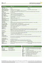
Type 

Torque 

Supply 

Motor running time  

Spring return 

Control mode 

Additional features  

Wiring diagram

InMax-8-F1 

  8 Nm


24..240 VAC/DC


3/15/30/60/120 sec. at 90° 

< 1 sec. at 90° 

On-off 

–  

SB 1.4/1.5

InMax-8-SF1 

  8 Nm


24..240 VAC/DC


3/15/30/60/120 sec. at 90° 

< 1 sec. at 90° 

On-off 

2 contacts (5/85°)  

SB 1.4/1.5

InMax-8-BF1 

  8 Nm


24..240 VAC/DC


3/15/30/60/120 sec. at 90° 

< 1 sec. at 90° 

On-off 

2 contacts (5/85°) + fire trigger 

SB 7.5/7.6

InMax-15-F1 

15 Nm


24..240 VAC/DC


3/15/30/60/120 sec. at 90° 

< 1 sec. at 90° 

On-off 

–  

SB 1.4/1.5

InMax-15-SF1 

15 Nm


24..240 VAC/DC


3/15/30/60/120 sec. at 90° 

< 1 sec. at 90° 

On-off 

2 contacts (5/85°)  

SB 1.4/1.5

InMax-15-BF1 

15 Nm


24..240 VAC/DC


3/15/30/60/120 sec. at 90° 

< 1 sec. at 90° 

On-off 

2 contacts (5/85°) + fire trigger 

SB 7.5/7.6

InMax-…-VAS 

Type as above but with stainless steel housing (AISI 316) gearbox parts in stainless steel, cable gland and hollow rivet nickel-plated

InMax-…-CTS 

Type as above but with aluminium housing and Amercoat paint, gearbox parts, cable gland and hollow rivet nickel-plated

InMax-   8 - F1

InMax-   8 - SF1

InMax-   8 - BF1

InMax- 15 - F1

InMax- 15 - SF1

InMax- 15 - BF1

InMax- ... - ... - VAS

InMax- ... - ... - CTS

Description size S

The InMax actuators are a revolution for safety, fire and shut-off 
dampers other motorized applications in chemical, pharmaceutical, 
industrial and Offshore-/Onshore plants, for use in safe areas.
IP66 protection, small dimensions, only 3,5 kg weight, universal 
functions and technical data, an integrated heater and an optional 
stainless steel housing guarantee safe operation even under difficult 
environmental conditions. High quality brushless motors guarantee 
long life.
All actuators are programmable and adjustable on site. Special tools or 
equipment are not required. Motor running times selectable or 
adjustable on site. The integrated universal  power supply is self 
adaptable to input voltages in the range of 24 to 240 VAC / DC. 
The actuators are 100% overload protected.
InMax-...-F1 actuators are equipped with spring return fail safe function. 
Futher the InMax-..-SF1 with integrated aux. switches for end position 
indication and the InMax-..-BF1 with an additional circuit to connect an 
external passive potential free thermostat Type InPro-TT-... Standard 
shaft connection is a double squared direct coupling with 12 × 12 mm.
Different accessories are available to adapt aux. switches, terminal 
boxes or adaptations for ball valves and throttle valves.

Application

Highlights

Summary of Contents for InMax Revolution

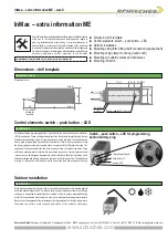
Page 1: ...0 sec at 90 1 sec at 90 On off 2 contacts 5 85 fire trigger SB 7 5 7 6 InMax 15 F1 15 Nm 24 240 VAC DC 3 15 30 60 120 sec at 90 1 sec at 90 On off SB 1 4 1 5 InMax 15 SF1 15 Nm 24 240 VAC DC 3 15 30 60 120 sec at 90 1 sec at 90 On off 2 contacts 5 85 SB 1 4 1 5 InMax 15 BF1 15 Nm 24 240 VAC DC 3 15 30 60 120 sec at 90 1 sec at 90 On off 2 contacts 5 85 fire trigger SB 7 5 7 6 InMax VAS Type as abo...

Page 2: ...operation of actuators with spring return danger of injury exists with release let go the allen key Integral heater integral heater controlled for ambient temperature down to 40 C Housing material aluminium die cast housing painted optional in stainless steel version AISI 316 Type InMax VAS amercoat painting type InMax CTS Dimensions L W H 210 95 80 mm for diagramm see extra information ME S Weigh...

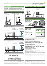
Page 3: ...0 VAC DC a Attention If you use this type of wiring the heater does not work in case of open contact S T Switch Push button Lamp for adjustment behind the blancking plug 10 position switch S Push button T 3 colour LED PA PA PA PA Example InMax 15 BF1 Requested parameter Torque 15 Nm Running time motor 30 sec 90 Result switch position S 02 See extra information EL S A Self adjustment of Angle of ro...

Page 4: ...t to the factory InMax actuators are equipped with an additional temperature sensor to stop the actuator before reaching this max temperature In this case the failure must be eliminated immediately on site H InPro TT The actuator works only with the temperature sensor type InPro TT Details see extra information ME Details see extra information ME InSwitch is an accessory to InMax actuators size S ...

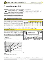
Page 5: ...ltage Uv V Formula for max cable length L at cable cross section A L A l Uv 18V 0 0714 Formula of needed cable cross section A at a cable length of L A 0 0714 l L Uv 18V The EL S data sheet contains additional information for ExMax RedMax and InMax actuators of the size S for the optimization and simplification in regard to planning installation and initial startup It provides influences of extern...

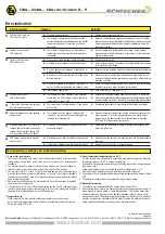
Page 6: ...wn operations l Attache power supply and turn on l Because of inadmissable operation the actuator drove out of safety relevant reasons into an irreversible condition and must be exchanged Accompanying new installation the ambient temperature has to be reduced accordingly Actuator does not work LED does not lights 01 Acuator does not work LED is red blinking 04 l The actuator has been mounted by te...

Page 7: ...d 12 12 mm 60 incl radius of bend for the cable All InMax actuators are equipped with a 10 position switch a push button and a multicolor LED for calibration These control elements are to be found cable laterally behind the two middle sectioned dummy plugs For operation these must be removed The calibration can be achieved despide lining up tension at the actuator It has to be of great concern tha...

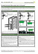
Page 8: ...postion must be selected by turning the actuator 180 Mounting 1 Affix tap hole M4 in accordance with drill template on the damper or to a mounting bracket 2 Adjust drive shaft of the actuator with the socket wrench that the drive stands perpendicular to the damper before pluging actuator on to the damper shaft 3 Plug actuator onto damper shaft and fix diagonally with 2 screws 4 Remove the socket w...

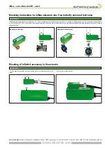
Page 9: ...res which require a special adaption Specification E X P L O S I O N P R O O F Schischek GmbH Germany Mühlsteig 45 Gewerbegebiet Süd 5 90579 Langenzenn Tel 49 0 9101 9081 0 Fax 49 0 9101 9081 77 E Mail info de schischek com InMax extra information ME size S 4 4 Mounting to a butterfly valve Mounting to a ball valve 4 Mounting instructions for InMax actuators size S on butterfly valve and ball valv...

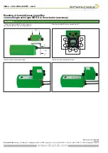
Page 10: ...9 0 9101 9081 77 E Mail info de schischek com InMax extra information ME size S Mounting of terminal boxes type InBox via mounting bracket type MKK S to the actuator accessory 2 2 B A 1 Screw mounting bracket MKK S to the actuator A then screw terminal box to the mounting bracket B Mounting bracket MKK S can be mounted every 90 Terminal box mounted above the actuator Terminal box mounted beside th...

Reviews: