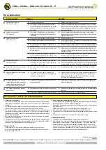
Error/Symptom
Reason
Solution
Over temperature, heating by low ambient temperatures
M.EZ-04.01-S-en-F1-extra-info EL
28-july-2011
Schischek GmbH
Germany, Mühlsteig 45, Gewerbegebiet Süd 5, 90579 Langenzenn, Tel. +49 (0)9101 9081-0, Fax +49 (0)9101 9081-77, E-Mail [email protected]
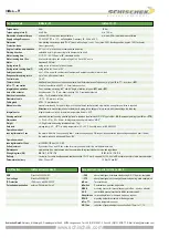
ExMax-.., RedMax-.., InMax extra information EL F1
Actuator does not work
LED ligths red
l
The actuator is operated by a too high ambient
temperature and the internal temperature sensor
responded
l
Shut off actuator and let temperature decrease, reduce ambient
temperature by suitable measures e.g. ventilation or other mounting
position of the actuator
02
Actuator does not work
LED lights green
l
3-Pos control signal is wired on both entrances
l
Required torque is greater than actuators torque
l
Control signals are not attached or attached on a
wrong conductor
l
Actuator is incorrect mounted and is blocked by an
external stop unit
l
Actuator is clocked with more than 20 impulses <0,5
per sec. and therefore adjusted into suspend mode
l
Interchanged supply lines
l
Readjust/correct circuit
l
Adjust a higher torque at the actuator if possible otherwise exchange
for a type with higher torque.
l
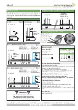
Examine rule and adjusting signal in accordance with attached diagram
l
Dismount actuator and testdrive without load for operability. Install
actuator accordingly that the power transmissions runs without external
blockade or torsion
l
Switch off supply voltage for at least 2 sec. thereby a reset is conducted
Readjust controller in order to extend control pulses
l
Wire 1 must be (-, N) and wire 2 (+, L)
03
05
06
07
Y-drive in the 3-pos mode can not gear
into intermediate positions
l
The conversion of constant mode on 3-pos-modus
was not set
l
Recalibrate the actuator in accordance with assembly instructions
08
Actuator sits diagonally on the squared
damper shaft
l
The actuators have an angle of rotation of 95°
inclusive 5° pre-tention. While assembling the pre-
loading was not considered
l
Dismount actuator of the damper, use the enclosed socket wrench to
draw up approx. 5° over the hand operated control device before
remounting on the damper shaft. Consider additional information
ME (size S) of the assembly instructions
A modulating actuator (Y) works with
reduced angle of rotation and already
reaches its end positions before 0 V/4
mA, respectively before 10V/20mA.
l
At start up no self adjustment of angle of rotation
was accomplished
l
Accomplish self adjustment of angle of rotation in accordance with
assembly instruction
LED flashes irregularly and actuator
does not work
l
Actuator does not receive sufficient supply voltage
l
Cable to long, voltage drop in the supply line to large
l
Increase line cross section or increase tension at the transformer/power
suply unit
l
Increase line cross section or increase tension
l
No power supply attached
l
The actuator is operated beyond ex-prevention
ambient temperature specifications and the internal
temperature sensor did irreversibly shut down
operations
l
Attache power supply and turn on
l
Because of inadmissable operation the actuator drove out of safety
relevant reasons into an irreversible condition and must be exchanged.
Accompanying new installation the ambient temperature has to be
reduced accordingly
Actuator does not work
LED does not lights
01
Acuator does not work
LED is red blinking
04
l
The actuator has been mounted by temperatures
of less than -20°C and did not reach is operating
temperatur of at least -20°C.
l
Ensure that a constant voltage supply on conductor 1--2 is existing.
l
Wait until the required operating temperature is achieved by the actuators
internal heating system.The actuator will start operating independently
E X P L O S I O N P R O O F
Error indication
I. 3 sec. motor running time
1. The 3 sec. motor running time mode is only in switch position 0 and 5 and at a constant
supply voltage on terminals 1 and 2 which must be in minimum for 1 minute applied
/available.
2. The actuator opens at voltage on terminal 3 (resp. closes), and closes at voltage on
terminal 4 (resp. opens ) depending on mounting position of the actuator.
3. The max. duty ratio is 10 % resp. 1 cycle / minute. Between two fully cycles to the same
direction there must be a minimum intermission of 1 minute. The actuator is blocked if
the break time is less than 1 minute. The release for the next cycle is made automatically
by an internal timing relay.
4. Same function is applied on spring return actuators . Faile safe operation is regarded
same as a motor running cycle.
5. If its tried to use the 1 wire On/Off methode in switch position 0 and 5, software changes
the running time temporarily and automatically to 15 sec. motor running time to protect
the actuator for overheating due to uncontrolled duty ratio.
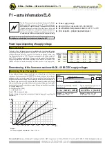
II. Temperature rise
While operating the ..Max actuator following parameters have to be aligned:
At overload resp. temperature rise the actuator will remain functionless until cooling.
During cooing the LED is red.
III. Use at low ambient temparature below -20°C
All ..Max actuators are equipped with a regulated integrated heating device designed
for employments down to -40°C ambient temperature.
The heater will be supplied automatically by connecting the constant voltage supply on
the clamps 1 and 2.
Following parameters are to be considered by ambient temperaure < 10°C:
1. After mounting the actuator must bei immediately electrically connected.
2. The actuator will only be activated after the operating temperature has reached at least
-20°C .
3. The adjustment options are only ensured after this heating up period.
IV.Mechanical protection
1. The actuator must be operated with an outside load of at least 5 Nm.
2. After installing the actuator to the damper/armature an automatic alignment has to be
accomplished, in order to obtain a gentle blockade/stop. This function protects the
damper/armature by reducing the end positions/blockade speed in order to avoid
mechanical overload. The actuator alignes specifically once with 90 sec./90° onto each
position, recognizes the blockade position in order to reduce the motor performance
during operation briefly before reaching the end/blockade position.
www.schischek.com


