Schischek GmbH Germany, Mühlsteig 45, Gewerbegebiet Süd 5, 90579 Langenzenn, Tel. +49 (0)9101 9081-0, Fax +49 (0)9101 9081-77, E-Mail [email protected]
www.schischek.com
E X P L O S I O N P R O O F
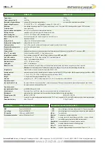
SB 7.5
SB 1.5
SB 1.4
SB 7.6
B
A
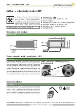
Type
Torques
InMax- 15-BF1
15 Nm
Running times Position of switch S
3 sec./90°
00 05
15 sec./90°
01 06
30 sec./90°
02 07
60 sec./90°
03 08
120 sec./90°
04 09
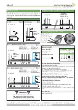
On-off 1-wire- spring circuit
1
2
°C
Circuit for
p potential free
push button on site
and safety temperature sensor
(Type InPro-TT-.. accessories)
4 5
Integrated aux. switches
max 24 V/3 A, 240 V/0,5 A
switching at 5° and 85°.
Supply at aux. switches must be the
same like supply of the actuator.
5 °
6
7 8
85 °
9
1
2
3
~
-
~
+
PE
heater
24...240 VAC/DC
InPro-TT-..
On-off - spring circuit
1
2
°C
push
button
circuit for
p potential free
push button on site
and safety temperature sensor
(Type InPro-TT-.. accessories)
4 5
5 °
6
7 8
85 °
9
1
2
3
~
-
~
+
PE
heater
24...240 VAC/DC
InPro-TT-..
Attention!
If you use this type of
wiring the heater does
not work in case of
open contact.
a
Never use actuators without external torque/force.
If 3 sec. motor running time is selected, the self adjustment
of Angle of rotation must be started and operation mode
of max. 10% ED must be guaranteed. (1 cycle per minute)
Attention
!
!
Integrated aux. switches
max 24 V/3 A, 240 V/0,5 A
switching at 5° and 85°.
Supply at aux. switches must be the
same like supply of the actuator.
a
1 2
Integral aux. switches
potential free contacts
switching at 5° and 85°
Angle of rotation
max. 24 V/3 A, 240 V/0,25 A
< 5 °
3
4 5
> 85 °
6
1
2
3
~
-
~
+
PE
heater
24…240 VAC/DC
push
button
On / Off
1
2
3
~
-
~
+
24…240 VAC/DC
PE
heater
PA
a
On / Off 1-wire
1
2
3
~
-
~
+
PE
heater
24…240 VAC/DC
a
Attention!
If you use this type of
wiring the heater does
not work in case of
open contact.
S
T
Switch – Push button – Lamp
for adjustment,
behind the blancking plug
10-position switch (S)
Push button (T)
3-colour LED
PA
PA
PA
PA
Example: InMax-15-BF1
Requested parameter:
Torque 15 Nm
Running time motor 30 sec/90°
Result: switch position (S) 02
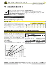
See extra information “EL-S”
A) Self adjustment of Angle of rotation:
Switch (S) into position 02, then push button (T) for minimum 3 seconds. The actuator
will drive into both end positions to be adjusted.
LED indicates green flashing. The actuator must be in position off.
Adjustment time needs approx. (90 sec. On, 3 sec. Off). After that, switch S into
position 00-09 in acc. with your required torque and running time.
B) Selection of running time and torque:
Put switch (S) into the correct/selected position in acc. to above table.
The selected parameter will work at next operation of the actuator.
Adjustment can be done even without supply voltage. If supply voltage is available
turn switch only if actuator is not running.
C) Additional information for 3-pos operation:
a closed = actuator goes ON
a opened = spring return mode
Direction depends on left/right mounting of the actuator to the damper/valve.
D) Function of a passive sensor in the circuit:
If the sensor opens the circuit the actuator runs into its safety end-position with spring
return.
Error indication
Function, adjustment and parameter
Parameter, Adjustment – Failure indication
Connection
Wiring diagram InMax-..-.F1 with integral aux. switches
InMax-..-.F1
InMax actuators are equipped with a universal supply unit working at a voltage range from
24 to 240 VAC/DC
.
The supply unit is self adjustable to the connected voltage!
The safety operation of the spring return function works if the supply voltage is cut or open
the wire no 3.
Electrical connection
Parameter selection


