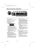
Name and Function of Each Part
POWER
G
H
I
8
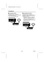
ETHERNET connector
Use this connector to connect the video
server to a hub, local server or network
server. Use a 10Base-T or 100Base-TX
(Category 5, UTP) cable to make the
connection.
9
ALL RESET button
This button restarts the system. The settings
that have been changed in the setting menus
are not affected.
F
VIDEO IN/OUT terminals
•
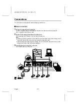
Video input terminals (VIDEO IN 1 – 4)
Connect these terminals to the output
terminals of the monitoring cameras.
•
Video output terminals (VIDEO OUT 1 – 4)
Connect these terminals to a monitor for
pass-through output of the images to the
monitor.
G
POWER indicator
This indicator illuminates when 12 V DC is
supplied to the power terminals.
H
PC card slot
Insert a memory card or wireless LAN card
into this slot. At the time of shipment from the
factory, a dummy card is inserted to prevent
dust and other foreign particles getting inside
the unit. If using a PC card, press the PC
card eject button to remove the dummy card
before inserting the PC card.
I
PC card eject button
L8NAA/XE
(VSP-SV2000P) GB 2003,
5,
12
– 6 –
English

