− 41 −
⑤
Read the value on the display.
⑥
After measurement, remove the red and black test pins from
the circuit measured.
⑦
Turn the function switch to the position of OFF.
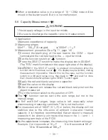
If the display will not change when an input signal is applied
(measurement is not possible), a probable cause is a blown fuse.
Since this instrument employs the means value system for its
AC voltage measurement circuit, AC waveform other than sine
wave may cause error.
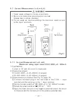
5-7-2 Current Measurement (A) Maximum rating input value DC/AC 10A
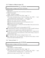
1. Never apply voltage to the input terminals.
2. Finish measurement within 45 seconds to prevent heat
generation.
3. Provide intervals 2 minutes or longer between measurements
to prevent heat generation. (Continuous measurement:max 5A)
4. Perform measurement with the leads kept straight to prevent
overheat.
WARNING
1) Applications
Current in DC and AC circuit is measured.
2) Measuring ranges
DCA: 4 10A (2 ranges), ACA: 4 10A (2 ranges)
3) Measurement procedure (See Fig 14, page 17)
①
Slide the safety cover of the PC20 to the left and insert the red
plug of the test leads to the 4 10A measuring terminal and the
black plug to the COM (
) terminal.
②
Set the function switch at "4 10A
/
" function.
③
Select the select switch at "
" (DC) or "
" (AC).
④
Apply the black test pin to the negative potential side of the
circuit to measure and the red test pin to the positive potential
side.
⑤
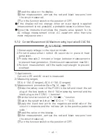
Read the value on the display.
⑥
After measurement, remove the red and black test pins from
the circuit measured.
⑦
Turn the function switch to the position of OFF.
Summary of Contents for PC20
Page 1: ...PC20 DIGITAL MULTIMETER 取扱説明書 INSTRUCTION MANUAL ...
Page 2: ......

