


− 37 −
5-4 Testing Diode ( )
Never apply voltage to the input terminals.
WARNING
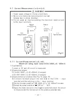
5-3 Resistance Measurement (
Ω
)
Never apply voltage to the input terminals.
WARNING
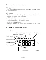
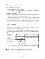
1) Application
Resistance of resistors and circuits are measured.
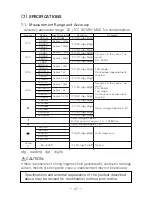
2) Measuring ranges
400
Ω
40M
Ω
(6 ranges)
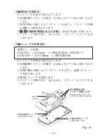
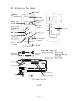
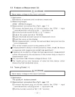
3) Measurement procedure (See Fig 8, page 11)
①
Connect the black plug of the test lead to the COM
input
terminal and the red plug to the
input terminal.
②
Set the function switch at "
Ω
/
/
" function.
③
Select the select switch at "
Ω
" (M
Ω
).
④
Apply the black and red test pin to measured circuit.
⑤
Read the value on the display.
⑥
After measurement, remove the red and black test pins from the
circuit measured.
⑦
Turn the function switch to the position of OFF.
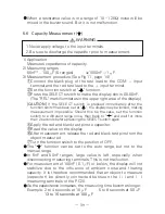
If measurement is likely to be influenced by noise, shield the object
to measure with negative potential (test lead black).
If a test pin is touched by a finger during measurement, measurement
will be influenced by the resistance in the human body to result in
measurement error.
The input terminals release voltage is about 0.4V.
The reading may vary because of external inductance when
measuring high resistance value.
1) Application
The quality of diodes is tested.
2) Measurement procedure (See Fig 9, page 12)
①
Connect the black plug of the test lead to the COM
input
terminal and the red plug to the
input terminal.
②
Set the function switch at "
Ω
/
/
" function.
Summary of Contents for PC20
Page 1: ...PC20 DIGITAL MULTIMETER 取扱説明書 INSTRUCTION MANUAL ...
Page 2: ......