− 39 −
When a resistance value is in a range of 10
120
Ω
, noise will be
mixed in the buzzer sound. But it is not malfunction.
5-6 Capacity Measurement ( )
1. Never apply voltage to the input terminals.
2. Be sure to discharge the capacitor prior to measurement.
WARNING
1) Application
Measures capacitance of capacity.
2) Measuring ranges
50nF*
100
F (5 ranges)
1000nF
1
F
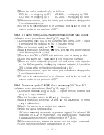
3) Measurement procedure (See Fig 11, page 14)
①
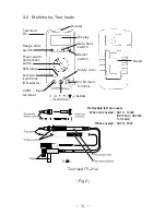
Connect the black plug of the test lead to the COM
input
terminal and the red test lead to the
input terminal.
②
Set the function switch at "
" function.
③
Press the SELECT switch to make the display show 00.00nF.
(The "REL" mark illuminates in the upper right area of the display.)
[CAUTION]
If the SELECT switch is pressed immediately after the
function switch has been set at " ", the display may be locked, making
measurement impossible. Should this be the case, set the function
switch to a different range once, then back to " " and wait for more
than 2 seconds before pressing the SELECT switch again.
④
Apply the red and black test pins to capacitor.
⑤
Read the value on the display.
⑥
After measurement, release the red and black test pins from the
object measured.
⑦
Turn the function switch to the position of OFF.
The "
" function can be set to the auto range, but not to the
manual range.
In 5nF and 50nF ranges, large value is left, especially when
disconnecting measuring terminals. This is not malfuction.
For measurement of 100nF (0.1
F) or below, the display will not
stabilize due to the influence of ambient noise and floating
capacity. It is therefore recommended that an object to measure
(capacitor) be directly connected between the (
) and (
)
measuring terminals of the PC20.
As the capacitance increases, the measuring time becomes longer.
Example: 2 to 4 seconds at 10
F
5 to 8 seconds at 50
F
Example:
13 to 16 seconds at 100
F
Summary of Contents for PC20
Page 1: ...PC20 DIGITAL MULTIMETER 取扱説明書 INSTRUCTION MANUAL ...
Page 2: ......


