background image

S&C Instruction Sheet 766-557    7

Establishing Wi-Fi Connection

The Wi-Fi transceiver provides secure wireless point-to-point communication to a wireless-
equipped personal computer operating under IEEE 802.11b standard. Transmission range 
is typically 150 feet or less. 

Click the IntelliLink software or LinkStart icon or select 

Program Start


>


S&C Electric 

>


LinkStart V3 

on the personal computer

.

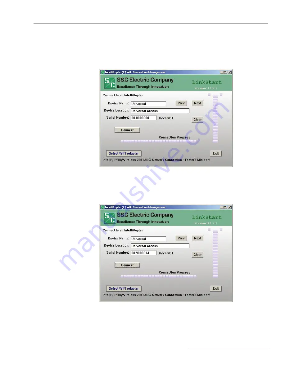
 The LinkStart connection screen will appear. 

See Figure 2.

Figure 2. LinkStart connection screen.

If the base memory module is unplugged:

 The default universal access serial number 

(00-0000000) will be used.


If the base memory module is plugged in:

 Type in 

its serial 

number (in this example 08-9000014).


Click 

Connect.

 The Wi-Fi connection process will begin. See Figure 3.

Figure 3. Wi-Fi connection in progress.

Summary of Contents for IntelliRupter PulseCloser SDA-4650R2

Page 1: ...mation Understanding Safety Alert Messages 3 Following Safety Instructions 3 Replacement Instructions and Labels 3 Overview 4 Setup 5 Establishing Wi Fi Connection 7 Serial Connection with a Docking S...

Page 2: ...ontained in S C s standard conditions of sale as set forth in Price Sheet 150 applies to IntelliRupter fault interrupter and its associated options except for the control group the protection and cont...

Page 3: ...E NOTICE identifies important procedures or requirements that can result in product or property damage if instructions are not followed Following Safety Instructions If you do not understand any porti...

Page 4: ...ffic between the protection and control module and the communication module using either a secure Wi Fi connection to your personal computer or a direct connection to your serial port equipped persona...

Page 5: ...the docking station to com municate with the protection and control module instead of using the Wi Fi connection a Remove the factory installed Wi Fi Serial to Control Wi Fi Serial to Comm jumper from...

Page 6: ...ed settings stored in the base memory module Step 9 Turn on the docking station power switch The red lamp on the docking station will light And the status indicator on the protection and control modul...

Page 7: ...re or LinkStart icon or select Program Start S C Electric LinkStart V3 on the personal computer The LinkStart connection screen will appear See Figure 2 Figure 2 LinkStart connection screen If the bas...

Page 8: ...s dim to bright while Wi Fi connection is being established After IntelliRupter fault interrupter recognizes the wake up message and its source it will proceed with authentication Encrypted messages a...

Page 9: ...m II Automatic Restoration System and loop resto ration can be entered into the protection and control module while it is connected to the docking station But only the settings actually suitable for t...

Page 10: ...he module is installed in the IntelliRupter fault interrupter base select Setup General Tab IntelliRupter See Figure 6 Select On Next Power up Use Settings From Control Remember to select Setup Valida...

Page 11: ...n Serial Cable PC Computer loaded with the latest IntelliRupter Fault Interrupter Software Step 1 Power the Docking Station and check that the red LED is on Step 2 Locate the serial jumper cable on to...

Page 12: ...the IntelliLink Setup Software application file Step 2 When the IntelliLink software is launched it is configured by default to connect to the control over a wireless link It automatically attempts t...

Page 13: ...he control you may receive a warning or an error message once a connection has been established If you receive an error message or were unable to download firmware through the Wi Fi connection to upgr...

Page 14: ...ut will eventually time out The connection status for DU is displayed in the lower left hand corner See Figure 12 Figure 12 Download Utility connection status shown on the Control Software Loader wind...

Page 15: ...nge the DNP Settings the Peer Addr or Our Addr settings Use the settings configured in Download Utility Step 5 When you have set all parameters on the Control Software Loader Communication Setup tab c...

Page 16: ...een shown in Figure 14 to see that the cor rect firmware has been installed Verification of Correct Operation Figure 14 The IntelliRupter Setup General Revisions screen After you complete verification...

Page 17: ...file Step 2 When the IntelliLink software is launched it is configured by default to connect to the control over a wireless link It automatically attempts to establish this connection Wait for the con...

Page 18: ...Make sure the Protocol is DNP Change if needed Change the RTU to self or 65532 Change the connection from UDP IP to Serial and then select the correct COM Port In this case the port is COM5 The Baud...

Page 19: ...nnect to the con trol with the IntelliLink software has generated errors or warning messages that indicate incorrect versions or maintenance mode conditions Step 1 Connect with the IntelliLink softwar...

Page 20: ...l appear It is recommended that you select the Yes button unless instructed otherwise by an S C representative Figure 23 Confirmation dialog box Step 5 After the software components have been installe...

Page 21: ...Software Versions screen shown in Figure 25 to see that the correct firmware has been installed Verification of Correct Operation Figure 25 The IntelliRupter Setup General Software Versions screen Aft...

Page 22: ...switch is turned off power cannot be turned on during that time Step 1 Turn off the docking station power switch Step 2 Carefully disconnect the protection and control module and the communication mod...

Page 23: ...ion Main screen The original Docking Station Catalog Number SDA 4650R1 was shipped with Base Memory Module BMM SDA 4781 which simulates the older IntelliRupter fault inter rupter without a Ground Trip...

Page 24: ......

Reviews: