4
Hardware Preview (1)
I/O Pin Assignment
Label Description
Definition
V Voltage
out
It provides 12 DC power to the sensors or any other devices.
If 12V is input to DC Jack, there will be 12V output from this
pin.
G Ground Ground
I1
Input 1
NC / NO; Default: NC; connect only to passive sensor to GND
I2
Input 2
NC / NO; Default: NC; connect only to passive sensor to GND
I3
Input 3
NC / NO; Default: NC; connect only to passive sensor to GND
I4
Input 4
NC / NO; Default: NC; connect only to passive sensor to GND
I5
Input 5
NC / NO; Default: NC; connect only to passive sensor to GND
I6
Input 6
NC / NO; Default: NC; connect only to passive sensor to GND
O1
Output 1
Low: 0V / High: 12V~24V; please see the reference circuit
O2
Output 2
Low: 0V / High: 12V~24V; please see the reference circuit
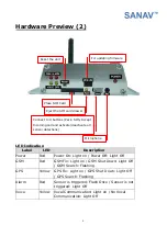
Connect to GPS
receiver, GM-158 with
TTL output.
GSM Antenna
12V~24V DC input


