EB 8048-2/-3 EN
41
Servicing
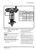
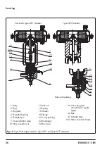
1. Undo the screws (34) on the valve
bonnet (20).
2. Lift the actuator (A) and valve bonnet
(20) together with the plug stem (3), plug
(2), and diaphragm (24) off the body
(1).
3.
"Actuator stem extends" fail-safe ac
-
tion:
guide the locking pin (Ø 3.5 mm)
through the hole located in the bottom
actuator section and the actuator stem.
"Actuator stem retracts" fail-safe action:
apply 6 bar signal pressure to the actua-
tor. Guide the locking pin (Ø 3.5 mm)
through the hole located in the bottom
actuator section and the actuator stem.
4. Unscrew the plug stem (3) together with
plug (2) and diaphragm (24) off the ac-
tuator stem and pull it out of the valve
bonnet (20).
5. Unscrew the actuator (A) from the valve
bonnet (20).
6. Remove locking pin.
For version with packing:
replace the
packing (see section 7.2.1).
7. Unscrew the threaded pin (6).
8. Unscrew the plug stem (3) from the plug
(2).
9. Remove diaphragm (24).
10. Apply a suitable lubricant to the thread
of the plug stem (3).
11. Screw a new plug (2) onto the plug stem
(3) using a suitable tool. Observe tight-
ening torques.
12. Mark the side mounting position.
13. Unscrew the plug stem (3) from the plug
(2).
14. Insert a new diaphragm (24) into the
new plug.
15. Screw the new plug (2) back onto the
plug stem (3) again using a suitable tool.
Align the plug stem with the mounted po-
sition mark made earlier. To do this,
clamp the plug into a suitable clamping
fixture and pull it with a suitable tool.
16. Remove the mounting position mark.
17. Secure the plug (2) with threaded pin
(6).
18. Check the concentricity of the plug (see
section 7.3).
19. Push the plug (2) together with plug stem
(3) and diaphragm (24) into the valve
bonnet (20).
20. Apply a suitable lubricant to the thread
of the valve bonnet (20).
21. Screw the actuator (A) onto the valve
bonnet (20).
22.
"Actuator stem extends" fail-safe ac
-
tion:
guide the locking pin (Ø 3.5 mm)
through the hole located in the bottom
actuator section and the actuator stem.
"Actuator stem retracts" fail-safe action:
apply 6 bar signal pressure to the actua-
tor. Guide the locking pin (Ø 3.5 mm)
through the hole located in the bottom
actuator section and the actuator stem.
23. Apply a suitable lubricant to the actuator
stem.
24. Screw the plug stem (3) together with
plug (2) and diaphragm (24) onto the


