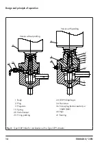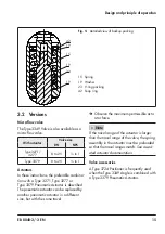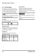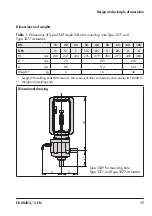
28
EB 8048-2/-3 EN
Mounting and start-up
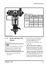
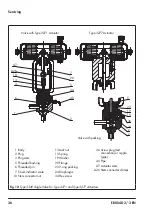
5. Unscrew the plug stem (3) together with
diaphragm (24) and plug (2) from the
actuator stem.
6. Remove locking pin.
7. Place the actuator and valve bonnet (20)
together with the plug (2), plug stem (3),
and diaphragm (24) onto the body (1).
8. Tighten the screws (34) on the valve bon-
net (20) gradually in a crisscross pattern.
Observe tightening torques.
9. For further instructions concerning
Type 3379 Actuator (pneumatic connec-
tions, alignment of the actuator, etc.)
u
5.2
Installing the valve into the
pipeline
5.2.1
Checking the installation
conditions
Pipeline routing
The inlet and outlet lengths vary depending
on the process medium. To ensure the control
valve functions properly, follow the installa-
tion instructions given below:
Î
Observe the inlet and outlet lengths (see
Table 5). Contact SAMSON if the valve
conditions or state of the medium process
deviate.
Î
Install the valve free of stress and with the
least amount of vibrations as possible. If
necessary, attach supports to the valve.
Î
Install the valve allowing sufficient space
to remove the actuator and valve or to
34
24
1
3
2
20
A
1
Body
2
Plug
3
Plug stem
20 Valve bonnet
24 Diaphragm
34 Screw
A
Actuator
Fig. 11:
Assembling Type 3349 Valve and
Type 3379 Actuator

