40
EB 8048-2/-3 EN
Servicing
3.
"Actuator stem extends" fail-safe ac
-
tion:
guide the locking pin (Ø 3.5 mm)
through the hole located in the bottom
actuator section and the actuator stem.
"Actuator stem retracts" fail-safe action:
apply 6 bar signal pressure to the actua-
tor. Guide the locking pin (Ø 3.5 mm)
through the hole located in the bottom
actuator section and the actuator stem.
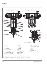
4. Unscrew the plug stem (3) together with
plug (2) and diaphragm (24) from the
actuator stem and pull it out of the valve
bonnet (20).
5. Unscrew the actuator (A) from the valve
bonnet (20).
6. Remove locking pin.
7. Compress the packing using a suitable
tool and remove the snap ring (42).
8. Pull all the packing parts out of the pack-
ing chamber using a suitable tool. Renew
the damaged parts and carefully clean
the packing chamber.
9. Check the plug and diaphragm for dam-
age. Replace them, if necessary (see sec-
tion 7.2.2).
10. Push the plug (2) together with plug stem
(3) and diaphragm (24) into the valve
bonnet (20).
11. Carefully slide the packing parts over the
plug stem into the packing chamber us-
ing a suitable tool.
12. Compress the packing using a suitable
tool and insert the snap ring (42).
13. Screw the actuator (A) onto the valve
bonnet (20).
14.
"Actuator stem extends" fail-safe ac
-
tion:
guide the locking pin (Ø 3.5 mm)
through the hole located in the bottom
actuator section and the actuator stem.
"Actuator stem retracts" fail-safe action:
apply 6 bar signal pressure to the actua-
tor. Guide the locking pin (Ø 3.5 mm)
through the hole located in the bottom
actuator section and the actuator stem.
15. Apply a suitable lubricant to the actuator
stem.
16. Screw the plug stem (3) together with
plug (2) and diaphragm (24) onto the
actuator stem. Observe tightening
torques.
17. Remove locking pin.
18. Place the actuator and valve bonnet (20)
together with the plug stem (3), plug (2),
and diaphragm (24) onto the body (1).
19. Apply a suitable lubricant to the hex
screws (34).
20. Tighten the hex screws (34) on the valve
bonnet (20) gradually in a crisscross pat-
tern. Observe tightening torques.
21. For version with Type 3724 Positioner:
initialize the positioner (
u
7.2.2
Replacing the dia
-
phragm and plug
Before replacing the diaphragm and plug,
remove the valve from the plant.
Note

