24
EB 8310-5 EN
Mounting and start-up
8. Depending on the direction of action:
Actuator stem extends
Apply a signal pressure that corresponds
to the lower signal pressure range value
to the connection on the bottom dia-
phragm chamber.
Actuator stem retracts
Apply a signal pressure that corresponds
to the upper signal pressure range value
to the connection on the top diaphragm
chamber.
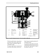
9. Screw on the stem connector nut (9) by
hand until it touches the actuator stem
(A7).
10. Turn the stem connector nut a further
quarter turn and secure this position with
the lock nut (10).
11. Position clamps of the stem connector
(A26) and screw them tight.
12. Align the travel indicator (84) with the tip
of the stem connector clamp.
5.2 Preloading the springs
By preloading the springs in the actuator, the
following can be achieved:
−
The thrust is increased (only actuators
with "stem extends")
−
In combination with a SAMSON valve:
the actuator travel range can be adapted
to a smaller valve travel range
Actuators that have already been preloaded
by SAMSON without mounting the valve are
labeled correspondingly.
Additionally, they can be identified by the
longer bolts with nuts protruding from the
bottom diaphragm case. They allow the
spring compression to be relieved evenly
when disassembling the actuator (see sec-
tion 9.3).
5.2.1 Compressing the springs
Risk of actuator damage due to the springs
being tensioned unevenly.
−
Distribute clamping bolts and nuts evenly
around the circumference.
−
Tighten the nuts gradually in a crisscross
pattern.
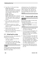
1. Distribute the long bolts (A22) evenly
around the circumference.
2. Screw the long nuts (A23) together with
one washer (A25) onto the clamping
bolts (A22) until they rest on the bottom
diaphragm case (A2).
3. To tension the springs evenly, tighten the
nuts (A23) gradually in a crisscross pat-
tern until both diaphragm cases (A1, A2)
rest on the diaphragm (A4). Hold the
bold head stationary with a suitable tool
and apply the tightening torque to the
nuts. Observe tightening torques.
4. Insert the short bolts (A20) through the
intended holes on the diaphragm cases
(A1, A2).
Note
NOTICE
!
Summary of Contents for 3277
Page 46: ...46 EB 8310 5 EN...
Page 47: ...EB 8310 5 EN 47...

