


30
EB 8310-5 EN
Operation
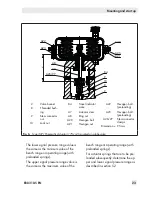
6.5.2 Reversal of the direction
of action from stem re-
tracts to stem extends
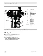
1. Lift the actuator off the valve. See sec-
tion 9.2.
2. Unscrew the nuts (A21) and bolts (A20)
on the diaphragm case.
3. Relieve the spring compression of actua-
tors with preloaded springs (see sec-
tion 9.3).
4. Lift off the top diaphragm case (A1).
5. Pull the diaphragm plate assembly con-
sisting of the actuator stem (A7), dia-
phragm plate (A5), and diaphragm (A4)
out of the bottom diaphragm case (A2).
6. Take the springs (A10) out of the bottom
diaphragm case (A2).
7. Clamp the bottom section of the actuator
stem (A7) into a vise using protective
jaws. Make sure that the actuator stem is
not damaged.
8. Unscrew and remove the nut (A33).
9. Remove the parts from the actuator stem
(A7) in the specified order:
−
Compressor (A35)
−
Diaphragm (A4)
−
Diaphragm plate (A5)
−
O-ring (A17)
−
Spacer (A36)
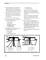
10. Place the parts on the actuator stem
in
the reverse order
as follows:
−
Compressor (A35)
−
Diaphragm (A4)
−
Diaphragm plate (A5)
−
O-ring (A17)
−
Spacer (A36)
Make sure that the seal lip of the dia-
phragm (A4) is inserted correctly be-
tween compressor (A35) and diaphragm
plate (A5).
To prevent the O-ring from being dam-
aged, use a suitable tool to slide the
O-ring onto the actuator stem and to po-
sition it correctly.
11. Screw the nut (A33) against the com-
pressor (A35). On tightening against the
glued hexagon nut (with 175 cm²) or on-
to the slotted nut (with 750 cm²), use a
suitable tool to hold it stationary. Ob-
serve tightening torques. Make sure that
the diaphragm does not turn.
12. Apply a suitable lubricant to the actuator
stem (A7).
13. Place the diaphragm plate assembly con-
sisting of the actuator stem (A7), dia-
phragm plate (A5), and diaphragm (A4)
into the bottom diaphragm case (A2).
14. Place the springs (A10) in the diaphragm
plate (A5), centering them in the intend-
ed recesses.
15. Place on the top diaphragm case (A1).
Ensure that the compressed air connec-
tions on the cases (A1, A2) are correctly
aligned with each other.
16. If necessary, preload the springs (see
section 5.2).
17. Fasten the top and bottom diaphragm
cases (A1, A2) together using the nuts
(A21) and bolts (A20). Tighten the nuts
evenly. Observe tightening torques.
Summary of Contents for 3277
Page 46: ...46 EB 8310 5 EN...
Page 47: ...EB 8310 5 EN 47...