


32
EB 8310-5 EN
Operation
handwheel, the upper spring range value
must not exceed 3.1 bar.
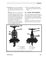
If you want to fit a handwheel to an actuator,
contact SAMSON's After-sales Service de-
partment.
6.6.1 Extending the actuator
stem manually
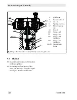
1. Loosen the lock nut (A66) to unlock the
handwheel (A60).
2. Turn the handwheel clockwise to extend
the actuator stem.
3. To change from manual to automatic op-
eration, put the handwheel into the neu-
tral position by aligning the pointer
(A55) with the groove on the stem con-
nector (A51).
4. Tighten the lock nut (A66) to lock the
handwheel.
6.6.2 Retracting the actuator
stem manually
1. Loosen the lock nut (A66) to unlock the
handwheel (A60).
2. Turn the handwheel counterclockwise to
retract the actuator stem.
3. To change from manual to automatic op-
eration, put the handwheel into the neu-
tral position by aligning the pointer
(A55) with the groove on the stem con-
nector (A51).
4. Tighten the lock nut (A66) to lock the
handwheel.
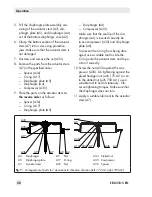
6.7 Travel stop
In the version with travel stop, the maximum
and minimum actuator travel can be limited
as follows:
Actuator
area
Direction
of action
Min. stop
in %
Max. stop
in %
175 cm²
Stem ex-
tends (FA)
0 to 85
0 to 125
Stem re-
tracts (FE)
0 to 85
0 to 100
750 cm²
Stem ex-
tends (FA)
0 to 125
0 to 125
Stem re-
tracts (FE)
0 to 100
0 to 100
6.7.1 Bottom travel stop
(minimum travel)
1. Loosen lock nut (A78) and remove cover
(A73).
2. Loosen top lock nut (A70).
3. Move actuator to the required position of
minimum travel.
4. Screw the bottom lock nut (A70) on as
far as it will go and lock this position
with the top lock nut (A70).
5. Attach the cover (A73) and retighten the
lock nut (A78).
Note
Summary of Contents for 3277
Page 46: ...46 EB 8310 5 EN...
Page 47: ...EB 8310 5 EN 47...