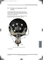
Removal and replacement of ADU modules
98-137654-A
Chapter 8: Service & maintenance
8-13
8888
Ser
vic
e & m
ain
ten
anc
e
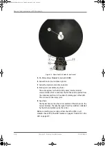
5. Zero Reference Module (x3, 2 in the previous figure, 1 in the next
figure) (ZRM) (not visible on photo).
In order to be able to find the predefined zero point of the
antenna direction, HALL sensors and corresponding magnets
mount in the gearwheels. Due to the magnetic hysteresis
behaviour of the hall sensor, the software will have to make the
magnets pass the hall sensor in both directions, and when use
the mean value as the zero point.
The ZRM features two LEDs; one for indication of power supply,
and one for indication of zero point.
6. DC-Motor Driver Module for elevation (on the bottom side)
(DDM).
As in item 3 above.
7. Elevation motor and encoder (not visible on photo).
8. Low Noise Block downconverter (LNB) (not visible on photo).
The LNB down-converter receives the Ku-band radio signal
(10.70- 12.75 GHz), which will be amplified and converted down
to a stacked L-band IF (950 - 5450 MHz). The conversion is
controlled by a DiSEqC-programmable Local Oscillator in the LNB
to obtain maximum flexibility in a global perspective where
several different LO's are used.
The Ku-band interface is a WR75 waveguide and the IF interface
is a 75 Ohm F connector. It has DC-power, and a DiSEqC control
signal is delivered via the IF cable. The L-band output is
delivered to the TIM.
9. Polarisation motor.
10. Polarisation Motor Module (PMM).
The PMM shall - based on inputs from the PCM - control the
angle position of the Polarization Mechanism Assembly (PMA).
The PMM board is:
• Communication slave of the ADU Bus also connecting the DC-
motor Driver Modules (DDM), the Inertial Sensor Module
(ISM) and the Pedestal Control Module (PCM).
• Driving a stepper motor, with micro stepping capability.
• Motor Filter which filters electrical noise and minimizes
acoustic noise.
• Decoding the HALL-sensor input from the Zero Reference
Module (ZRM).
• Decoding the input from the Optical Rotation Encoder (ORE).
11. Inertial Sensor Module (ISM).
SAILOR100TM.book Page 13 Tuesday, January 29, 2013 2:44 PM
Summary of Contents for 100
Page 1: ...TRAINING INSTALLATION SERVICE MANUAL SAILOR 100 Satellite TV ...
Page 2: ......
Page 13: ...Table of contents 98 137654 A xi SAILOR100TM book Page xi Tuesday January 29 2013 2 44 PM ...
Page 14: ...Table of contents xii 98 137654 A SAILOR100TM book Page xii Tuesday January 29 2013 2 44 PM ...
Page 215: ...Appendices SAILOR100TM book Page 1 Tuesday January 29 2013 2 44 PM ...
Page 216: ...SAILOR100TM book Page 2 Tuesday January 29 2013 2 44 PM ...
Page 254: ...Glossary Glossary 4 98 137654 A SAILOR100TM book Page 4 Tuesday January 29 2013 2 44 PM ...
Page 261: ......

