SAILOR 100 Satellite TV system
98-136280-B
Chapter 2: Introduction
2-5
2222
In
tr
oducti
o
n
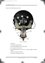
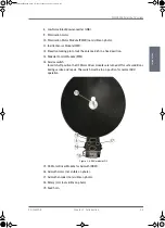
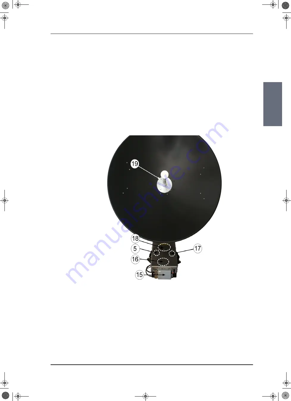
8. Low Noise Block downconverter (LNB).
9. Polarisation motor.
10. Polarisation Motor Module (PMM) (not visible on photo).
11. Inertial Sensor Module (ISM).
12. Elevation locking pin to lock the antenna dish in a fixed position.
13. Pedestal Control Module (PCM).
14. Service switch.
In switch-off position the DC Motor Driver modules are turned off for safe conditions
during service and repair. The switch must be in on position for normal ADU
operation.
15. DC-Motor Driver Module for Azimuth (DDM).
16. Azimuth motor (not visible on photo).
17. Azimuth encoder (not visible on photo).
18. Rotary joint (not visible on photo).
19. Feed horn.
Figure 2-4: ADU modules 2/2
SAILOR100IM.book Page 5 Friday, January 18, 2013 10:28 AM
Summary of Contents for 100
Page 1: ...INSTALLATION MANUAL SAILOR 100 Satellite TV ...
Page 2: ......
Page 8: ...vi 98 136280 B SAILOR100IM book Page vi Friday January 18 2013 10 28 AM ...
Page 141: ...Appendices SAILOR100IM book Page 1 Friday January 18 2013 10 28 AM ...
Page 142: ...SAILOR100IM book Page 2 Friday January 18 2013 10 28 AM ...
Page 178: ...Glossary Glossary 4 98 136280 B SAILOR100IM book Page 4 Friday January 18 2013 10 28 AM ...
Page 185: ......

