


SafanDarley E-Brake
Transport, installation, commissioning
Instruction manual SafanDarley E-Brake Premium 100-3100 100Pr 2019
73
5.1.
TRANSPORTATION
The SafanDarley E-Brake press brake has been packed properly for
transportation by truck or for overseas transportation.
5.1.1.
INTERNAL TRANSPORT IN YOUR COMPANY
Observe the following rules for transport inside the building
The way of handling
Weight: refer to technical specifications, § 1.2.1
Dimensions: refer to main measurements and foundation measurements
§ 1.2.2
5.1.2.
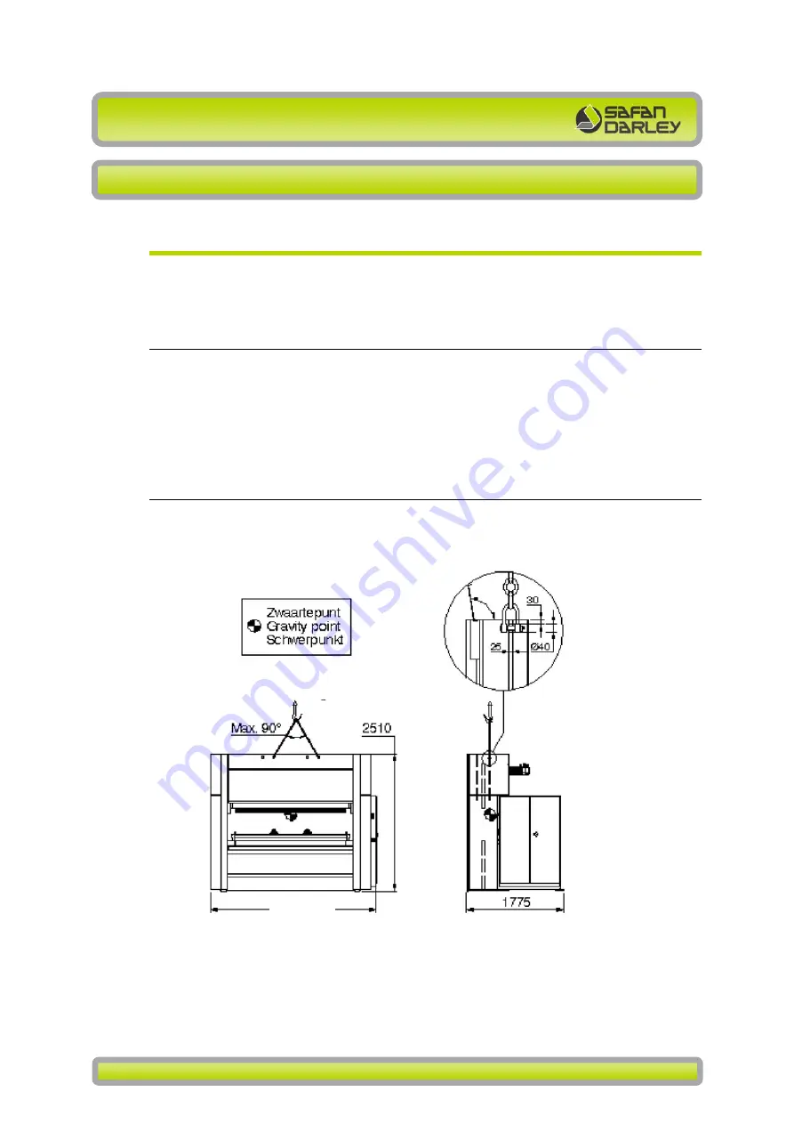
HOISTING
Use the crane holes in the back bridge next to the electro cabin and from that
point the third hole. In case of a machine with a tool cabinet use the holes next
to the electro cabinet and next to the tool cabinet.
Figure
5-1 Transport and hoisting instructions press brake
1. Upper crane holes for hoisting
2. Lash hooks for securing the press brake during transport.
After transport the lash hooks should be disassemble and stored in the electro
cabinet.
4080
7500