77
Section 3 - operation
Configuring Cutter for Milling (Planing)
1. Raise the cutter and secure it with the lock-
ing arm.
2. Secure the front of the cutter chassis with
safety stands.
3. Shutdown the truck and place it in the service
position.
4.
Remove rumble teeth and install planing (flat)
teeth. If planing teeth are already installed,
inspect the teeth and ensure they are in good
condition and tight.
5. Install or remove cutting teeth if necessary to
set the width of the cut.
6. Rotate eccentrics to TDC (Top Dead Center).
Monitor PLC as eccentrics are rotated. Con-
troller shows “ON” when eccentric is at TDC.
7. Lock Eccentrics. This is done by loosening the
1” jam nut on each threaded pin located on the
counter balance weights. Turn the threaded pin
clock wise until fully engaged with the action
control arm.
8. Open eccentric relieve valve. Turn the valve
all the way out (5.5 turns counter clockwise).
This is necessary because the eccentrics are
locked and cannot turn.
9. Install milling chassis and depth adjusting
wheels
10. Activate the Hydraulic System.
11. Unlatch the Cutting Head locking arm and
lower the cutting chassis to the pavement.
12. Adjust the down pressure. The pressure re-
quired for milling is much less than pressure
required for rumbling. Reducing down pressure
will result in less noticeable wheel marks in the
surface, however you should have 200-500 psi
(14-35 BARS) of down pressure for cutter sta-
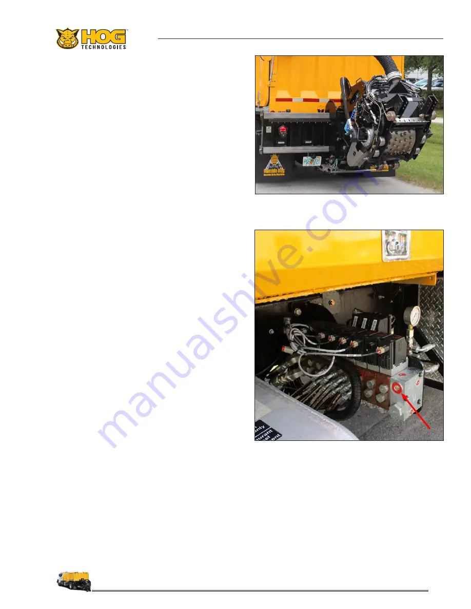
bility. The valve is located behind the hydraulic
manifold next to the frame. Down pressure is
displayed on the main control screen.
13. Adjust the trim pressure (no less than 100
psi). The valve is located in the center behind
the hydraulic manifold. Use the manual pres-
sure gauge at the valve to set the pressure.
14. Adjust cutting depth. Max depth is 3/8.”
Cutter Configured For Planing
Hydraulic Manifold & Manual Down Pressure Valve
15. Adjust vacuum height. (Trucks equipped with
optional vacuum recovery)
16. Program the controller for the desired cut
pattern.
Summary of Contents for RH7500
Page 1: ...RH7500 Operations Manual ...
Page 2: ......
Page 6: ...6 NOTES ...
Page 10: ...10 NOTES ...
Page 19: ...19 Section 1 Safety Information ...
Page 20: ...20 NOTES ...
Page 108: ...108 NOTES ...
Page 150: ...150 NOTES ...
Page 155: ...155 Appendix 3 Tools Spare Parts ...
Page 156: ...156 Appendix 3 Tools Spare Parts ...
Page 158: ...158 NOTES ...
Page 163: ......


