CLASSIC-LINE
ECO-LINE
Installation Guide
12
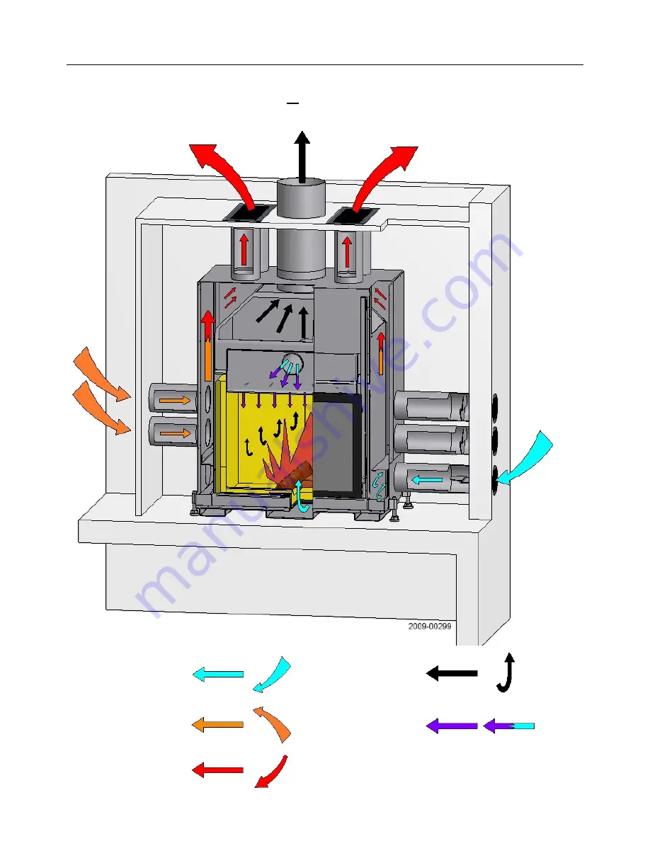
Fireplace type:
Fireplace S, type A/B2
Operating modes:
open
or
closed
(→ closed in the diagram)
External air
Ambient air
Convection air
Airwash air
Flue gas
Page 1: ...es S type 15 Fireplaces K type 16 Appliances on a socle 17 Sections for fireplaces with self closing door A1 B1 18 Sections for fireplaces without self closing door A B2 19 Fitting the sleeves 20 Fiit...
Page 2: ...Jade Front Saphir Front 39 Saphir Giant Saphir Giant 500 41 Lumo Front 40 Jade Tunnel Saphir Tunnel 41 Prisma Prismalo 500 43 Ellipse 44 720 Compact 45 720 46 720 Giant 47 Pi Classic 48 Pi Compact 49...
Page 3: ...type Non automatically closing fireplace door VL Combustion air KL Convection air BImSchV German law relating to protection against emissions D LRV Swiss law relating to air purity CH S fireplace Fir...
Page 4: ...some images may differ from your installation Hatching Pictograms NOTICE Handy information and advice NOTICE Use a protective glove WARNING Warns of a very hot surface WARNING Potential risk for the...
Page 5: ...ce Hot air vent Hearth Concrete base Thermal insulation layer Thermal insulating layer from the connector Deflector Hot air chamber Hot air duct S fireplaces Throat Hearth door Decorative beam Casing...
Page 6: ...aws and regulations regarding fire precautions chimney sweep Laws and regulations regarding fire insurance It is the fitter s responsibility to ensure conformity with the laws and regulations in force...
Page 7: ...that can be opened or they are directly or indirectly connected to other rooms which can provide combustion air intake If the fireplace is installed in an apartment or similar the combustion air inta...
Page 8: ...ensions of the chimney flue for the installation of a fireplace insert Calculations for type AI fireplace inserts are based on the volume of combustion air when the fireplace is operating with its doo...
Page 9: ...lled K fireplaces In this system the con vection air is taken in through a cavity in the fireplace casing and comes out into the room through vents in the fireplace apron If the fireplace insert also...
Page 10: ...CLASSIC LINE ECO LINE Installation Guide 12 Fireplace type Fireplace S type A B2 Operating modes open or closed closed in the diagram External air Ambient air Convection air Airwash air Flue gas...
Page 11: ...CLASSIC LINE ECO LINE Installation Guide 13 Fireplace type Fireplace S type A B2 Operating modes open or closed open in the diagram External air Ambient air Convection air Airwash Flue gas...
Page 12: ...CLASSIC LINE ECO LINE Installation Guide 14 Fireplace type Fireplace S type A1 B1 Operating modes closed only External air Ambient air Convection air Airwash air Flue gas...
Page 13: ...amount of air required The convection air outlet sleeves KL are factory fitted NOTICE The lids of not used open ings may never be taken away Convection air inlets Attachments for fresh air units optio...
Page 14: ...dust free and abrasion resistant For casings made of heat storage and radiation materials for which a convection circuit is generally not fit ted there must be a sufficient supply of external air to t...
Page 15: ...t KL Der Eintrittsstutzen f r die Verbren nungsluft VL ist bereits ab Werk montiert NOTICE The lids of not used openings may never be taken away For a trouble free open use of the fireplace the room m...
Page 16: ...2 Lumo S K 1 2 0 2 175 cm2 350 cm2 0 cm2 350 cm2 Pi Classic V S 1 4 0 4 175 cm2 700 cm2 0 cm2 700 cm2 Pi Compact V S 1 4 0 4 175 cm2 700 cm2 0 cm2 700 cm2 Pi ccolo Classic V S 1 2 0 2 123 cm2 350 cm2...
Page 17: ...ccolo Compact V S 1 1 1 2 123 cm2 175 cm2 175 cm2 350 cm2 Prisma S K 1 2 2 4 175 cm2 350 cm2 350 cm2 700 cm2 Prisma V 1 1 1 2 175 cm2 175 cm2 175 cm2 350 cm2 Prismalo 500 S K 1 2 1 3 175 cm2 350 cm2...
Page 18: ...250 C 1 Use a hammer to break out the blanking piece 2 Remove the blanking pieces 3 Install the 150 mm air sleeves 4 Fit the sleeve tabs into the slots in the opening 5 Fold down all the tabs 90 NOTI...
Page 19: ...itted 2 You can install one or two addi tional fresh air units Make sure you remove the corresponding blanking piece when positioning the unit on the left and or on the right 4 Fit each fresh air unit...
Page 20: ...l not operate prop perly in open or closed door modes If the fitter estimates that ducts of smaller diameter will satisfy combustion air requirements then any such installation is at his own risk and...
Page 21: ...hen the fireplace is fitted with the AIR Direct system VL in this case Hmax 6 m from the top of the hearth if the fireplace projects above the suction source If the fireplace uses a convection air sys...
Page 22: ...hat a flue of smaller section will satisfy requirements then any such installation is at his own risk and responsibility New chimney flues of 25 or 30 cm with a useful length of L 8 m or over and with...
Page 23: ...least 700 C Thermal insulating materials that are in contact with circulating hot air on all the K type fireplaces must also be fitted with an abrasion resistant lining e g metal plates with permanen...
Page 24: ...e V S K 3 12 0 10 7 12 2 Jade Front S K 3 12 0 10 6 12 2 Jade Tunnel S K 3 12 0 10 7 12 2 Larimar Front S 3 12 6 10 8 12 2 Lumo S K 3 12 0 10 6 12 2 Pi Classic Compact V S 3 12 4 0 10 6 11 12 2 Pi cco...
Page 25: ...ck concrete or similar material The protective wall must be laid seamlessly to cover the whole of the building wall inside the appliance casing cavity The thermal insulation between the protective wal...
Page 26: ...Front S 3 6 8 10 6 2 Ellipse V S K 3 0 7 6 2 Jade Front S K 3 0 6 6 2 Jade Tunnel S K 3 0 7 6 2 Larimar Front S 3 6 8 6 2 Lumo S K 3 0 6 6 2 Pi Classic Compact V S 3 4 0 6 11 6 2 Pi ccolo Classic Com...
Page 27: ...the insulation for inflammable building walls or walls requiring a protective covering and seamlessly covers the whole of the building wall inside the fireplace surround cavity Ceiling D The room ceil...
Page 28: ...l and thermal insulation to the front of an inflammable wall are replaced by substitute thermal insulation the insulation must be ap plied in two layers and the panel joints staggered When certified t...
Page 29: ...mic fireplaces and stoves Construction material rating EN 4102 4 A1 non inflammable Apparent density 10 EN 1094 4 375 kg m3 Porosity EN 1094 4 ca 90 Compression strength EN 1094 5 1 15 MPa Conductivit...
Page 30: ...s to be respected towards the fire opening On corner models as e g 720 720 Giant 720 Compact Ellipse etc if the side distances cannot be realized the inflammable lin ing must be put to the wall If a f...
Page 31: ...be respected from the side elements of the heating installation This distance must be exposed to an air stream that no heat congestion can ap pear X cm X cm Axinit Front S 170 Prisma V S K 80 Ellipse...
Page 32: ...th the speed regu lator supplied with it The surface on which the fireplace is to be installed must be statically load bearing An appliance must not be laid directly on a floating floor Electric wirin...
Page 33: ...r adjustable legs and retract them completely they must not extend past the appliance jacket Using the carrying handles and or straps to move the appli ance to where you wish to install it Check that...
Page 34: ...the fireplace using the four ad justable feet and a spirit level Connecting up the external air Follow the instructions on pages 15 to 22 to connect up the external air Fit the fresh air regulators as...
Page 35: ...mney flue thereby facilitating air circulation If the exhaust duct goes through construction elements containing inflammable materials cover the duct with a mineral material such as concrete extending...
Page 36: ...st meet the required thermal resistance standards and not produce odours when heated over time This is why materials containing plastics should be avoided Decorative beams Wooden beams must be protect...
Page 37: ...pletely to the left 2 Insert the left rear panel push it in completely to the left 6 Insert the left base panel Centre the 2 base panels Ensure the play is evenly distributed 1 Insert the left side pa...
Page 38: ...t 5 insert the rear central panel Align the three vertical panels Align the side panels 6 Insert the left base panel push in completely to the left 8 Insert the central base panel Align all the base p...
Page 39: ...nel push in completely to the left 2 Insert the two rear panels push them in completely to the left 3 Insert the two right side panels align all the panels 1 Insert the two left side panels push them...
Page 40: ...ternal chamotte retaining brackets on the back of the hearth 1 Remove the two external chamotte retaining brackets on the back of the hearth 2 Insert and centre the two left side panels 3 Insert and c...
Page 41: ...eft side panel slide it completely to the back 3 Insert the right side panel slide it completely to the back 4 Insert the right base panel 5 Insert the left base panel ensure the play is evenly distri...
Page 42: ...odel the same proce dure has to be applied 1 Insert the side panel pull to the front until behind the metallstrip 2 Insert lower back panel slide left against the side panel 4 Insert right base panel...
Page 43: ...tructions on page 52 1 Insert lower deflector Vermiculite 3 piece Lay on the L profile in the back and on the air channel 3 Front view Side view Upper deflector Lower deflector Thermobrikk WARNING Cha...
Page 44: ...e base panels Ensure the play is evenly distributed 3 Insert the top part of the rear panel align with the bottom part 6 Fit all the retaining brackets Fit the deflector 1 Insert the left side panel p...
Page 45: ...720 Giant 5 Insert the right hand base panel push in completely to the right 6 Insert the base panel push in completely to the left 4 Insert the left rear panel Ensure the play is evenly distributed...
Page 46: ...at the play is evenly distributed 5 Fit the deflector 2 Insert front base panel slide completely forward 3 Insert rear base panel slide base parts together distribute play evenly 6 Center deflector an...
Page 47: ...enly 2 Insert left back panel center both back panels 1 Insert right back panel slide completely to the right 4 Insert right base panel slide completely tot the right 5 Insert left base panel slide ba...
Page 48: ...ssic 3 Fit all retainig brackets 4 Fit the deflector 5 Distribute play evenly 2 Insert base panel distribute play evenly 1 Insert back panel distribute play evenly WARNING Chamotte panels must not be...
Page 49: ...ct 4 Fit the deflector 5 Distribute the play evenly 3 Fit all retaining brackets 2 Insert base panel ditribute play evenly 1 Insert back panel distribute play evenly WARNING Chamotte panels must not b...
Page 50: ...een back and sidewall Insert wall parts in the combustion chamber Next to the fireplace opening slide the element behind the steel strip Custom cut parts must always be placed in front next to the fir...
Page 51: ...hed a number of final steps need to be carried out Final visual inspection of the installation Functional test of the glass panel and unwanted noise by raising and lower ing it several times Functiona...
Page 52: ...s will ex pand or contract and may produce cracking noises These noises can vary in intensity according to the type of fireplace Data plate To ensure prompt after sales service we would ask you to giv...
Page 53: ...nd thermal insulation Except when stipulated otherwise see below the guide lines and instructions given above also apply to heat storage systems Air circulation System and operating modes Page 11 R eg...
Page 54: ...1 2 175 cm2 350 cm2 720 Compact 1 2 175 cm2 350 cm2 720 ECO 1 2 175 cm2 350 cm2 720 Giant 1 2 175 cm2 350 cm2 The fresh air duct must be drawn in from behind to the fresh air units The height differen...
Page 55: ...e wall must seamless ly cover the whole of the building wall inside the fireplace casing cavity Thermal insulation of a thickness of 10 cm between the protective wall and the fireplace inset must be l...
Page 56: ...covers the whole of the building wall inside the fireplace casing cavity Ceiling The room ceiling must be at least 12 cm thick If the fireplace casing cavity above the appliance extends to the ceiling...
Page 57: ...the jacket See also the dia gram on page 48 The cover will be made with heat stor age panels and can be thermally insu lated on top depending on the type of appliance The cover sits statically on the...
Page 58: ...To ensure even heat distribution a gap of between 4 and 12 cm should be left between the outside of the jacket and the inside of the casing Ensure there is adequate internal air circulation between t...
Page 59: ...ght kg 387 390 305 Technical characteristics Nominal heating power kW 11 0 11 0 13 0 Efficiency 80 2 80 9 81 0 CO 13 by O2 Volume mg Nm3 1125 1250 1125 Dust 13 by O2 Volume mg Nm3 21 23 23 0 Mass flow...
Page 60: ...kg 400 Technical characteristics Nominal heating power kW 11 0 Efficiency 80 0 CO 13 by O2 volume mg Nm3 750 Dust 13 by O2 volume mg Nm3 24 Mass flow of flue gases closed open g sec 8 6 23 8 Flue gas...
Page 61: ...eristics Nominal heating power kw 13 0 11 0 11 0 11 0 11 0 Efficiency 83 0 80 3 80 1 80 2 80 2 CO 13 by O2 Volume mg Nm3 1250 750 1250 750 750 Dust 13 by O2 Volume mg Nm3 21 0 22 0 20 0 26 0 26 0 Mass...
Page 62: ...313 Technical characteristics Nominal heating power kW 13 0 10 0 10 0 10 0 Efficiency 80 0 78 4 78 2 78 1 CO 13 by O2 volume mg Nm3 1250 750 875 1250 Dust 13 by O2 volume mg Nm3 16 0 25 27 28 Mass fl...
Page 63: ...ght kg 339 249 Technical characteristics Nominal heating power kW 10 0 10 0 Efficiency 78 0 78 0 CO 13 by O2 volume mg Nm3 750 750 Dust 13 by O2 volume mg Nm3 23 23 Mass flow of flue gases closed open...
Page 64: ...echnical characteristics Nominal heating power kw 11 0 11 0 9 0 9 0 Efficiency 78 9 79 3 79 5 79 5 CO 13 by O2 volume mg Nm3 875 1250 1250 1250 Dust 13 by O2 volume mg Nm3 30 37 40 40 Mass flow of flu...