RUDETRANS RLSS-301 User Manual Download Page 23


23 


- The hydraulic oil must be replaced one time each year. 
The oil level should always be kept at upper limit  
position. 

- Гидравлическое масло следует менять ежегодно. 
Уровень масла постоянно должен находиться выше 
минимума. 


The machine should be lower to the lowest 
position when replace hydraulic oil, then let  
the old oil out, and should be filtering the 
hydraulic oil. 

При замене гидравлического масла подъёмник 
должен быть опущен в крайнее нижнее положение, 
затем следует удалить отработанное масло и залить 
новое. 

- Each time checks the agility and reliability of pneumatic 
safety equipment. 

- Каждый раз контролируйте качественность 
зацепления зубьев фиксатора. 


Chapter 8 

FAILURE AND RESOLUTIONS

Глава 8 НЕИСПРАВНОСТИ И ИХ УСТРАНЕНИЕ


Only skilled and having been trained 
personnel is allowed to perform the 
operations.  

Только опытный и уполномоченный персонал 
допускается к выполнению поиска и устранения 
неисправностей. 

Trouble  

Cause and 
Phenomena 

Resolutions 

Неисправн
ость 

Причина 

Решение 

1) Connection 
of power 
supply wires 
or zero wire is 
not correct. 

Check and correct wire 
connection. 

1) Не подаётся 
электропитани
е или нулевой 
провод не 
присоединён.  

Проконтролируйте 
корректность 
подключения 

2) The AC 
contactor in 
the circuit of 
the motor 
does not pick 
up. 

If the motor operates 
when forcing the 
contactor down with an 
isolation rod, check the 
control circuit. If the 
voltage at two ends of the 
contactor coil is normal, 
replace the contactor. 

2) Не 
срабатывает 
контактор в 
цепи 
включения 
мотора 

Если мотор работает 
когда контактор 
принудительно опущен 
при помощи 
изолированного рычага, 
проверьте 
управляющий контур. 
Если напряжение на 
двух концах контактора 
нормальное, замените 
контактор. 

The motor 
does not 
run in 
lifting 
operation. 

3) The limit 
switch is not 
closed. 

Short-circuit terminal 10 
and 0, which are 
connected with the limit 
switch, and if the trouble 
disappears, check the 
limit switch, wires and 
adjust or replace the limit 
switch. 

Мотор не 
вращается 
при 
подъёме 

3) Концевик не 
закрывается 

Соедините клеммы 10 и 
0, которые соединены с 
концевиком, и если 
неисправность 
исчезает, проверьте 
концевик, провода и 
отрегулируйте или 
замените концевик. 

1) The motor 
turns reverse. 

Change the phases of 
the power supply wires. 

1) Мотор 
вращается в 
противоположн
ом 
направлении 

Поменяйте фазы 
проводов 
электропитания 

2) Lifting with 
light load is 
normal but no 
lifting with 
heavy load. 

The set safe pressure of 
the overflow valve may 
be increased by turning 
the set knob right ward 
slightly. 
The spool of the lowering 
solenoid valve is stuck 
by dirt. Clean the spool. 

2) Подъём с 
небольшим 
весом 
происходит 
нормально, а 
тяжёлый вес 
не 
поднимается 

Уровень безопасного 
давления может быть 
увеличен плавным 
вращением 
регулировочного винта 
в правую сторону. 
Катушка э/м клапана 
опускания засорилась. 
Очистите катушку.  

In lifting 
operation, 
the 
motor 
runs, but 
there is 
no lifting 
movement. 

3) The 
amount of 
hydraulic 
oil is not 
enough. 

Add hydraulic oil. 

Мотор 
работает, 
но 
подъёма не 
происходи
т 

3) 
Недостаточное 
количество 
гидравлическог
о масла. 

Добавьте 
гидравлическое масло. 


Summary of Contents for RLSS-301

Page 1: ...Small scissor lift RLSS 301 3 0T RLSS 301 3 0 USER S MANUAL Operating Manual Instructions Ref B3 GC 3 0SS user s manual 20090821 19 2012 Serial No Year of Manufacture...

Page 2: ...peaking users However if you have any questions remarks or notes caused by this manual please contact our specialists immediately RUDETRANSSERVICE Ltd Russia 173003 Velikiy Novgorod B Saint Petersburg...

Page 3: ...y 3 11 Chapter 4 Installation 4 15 Chapter 5 Adjustment 5 18 Chapter 6 Operation 6 21 Chapter 7 Maintenance and care 7 22 Chapter 7 Failure and resolutions 8 23 Chapter 9 Appendix 9 26 9 1 Hydraulic s...

Page 4: ...hat all items specified in the delivery notes are included In case of missing parts possible defects or damage due to transport the person in charge or the carrier must be immediately informed Further...

Page 5: ...ized personnel from the licensed dealer or an service center authorized by the manufacturer The manufacturer declines all responsibility for injury to persons or damage to vehicles or objects when any...

Page 6: ...t for hydraulic failure and over loading So when the oil pipe bursts the machine will not fall quickly Use high quality hydraulic or electric element parts made in Italy Germany Japan and so on Own ma...

Page 7: ...lift weight kg 3000 3 Main machine Lift height mm 960 4 Platform initial height mm 105 5 Platform length mm 1450 6 Platform width mm 530 7 Lifting time s 50 8 Descent time s 60 9 Overall length mm 204...

Page 8: ...0 5A 220 10A Max Frequency Hz 50 Poles 4 Speed 1450 Building shape B14 Insulation class F When connecting the motor refer to the enclosed diagrams and the motor direction is clockwise PUMP Type P4 3 M...

Page 9: ...Clean the basic layer thickness of concrete 150mm the leveling of whole length 10mm 150 10 Remarks 1 Fix ground bolts before loading 1 2 The control box can be placed on the left or right side 2 Pict...

Page 10: ...ifting weight is 3000Kg 3000 THE MAX DIMENSION OF VEHICLE The following diagrams illustrate criteria used to define the operating limits of the lift The lower parts of the vehicle underbody could inte...

Page 11: ...s for personnel or lifting personnel Use as a press for crushing purposes Use as elevator Use as a lift jack for lifting vehicle bodies or changing wheels The manufacturer is not liable for any injury...

Page 12: ...to persons and or damage the lift the vehicle or other property RISK OF ELECTRIC SHOCK a specific safety notice placed on the lift in areas where the risk of electric shock is particularly high Risk...

Page 13: ...0 Picture 9 Picture 10 There is nothing abnormal should be left on the safety modules to prevent safety gear from occlude normally RISKS FOR PERSONNEL This heading illustrates potential risks for the...

Page 14: ...t and also the platforms must be kept clean Remove any oil spills immediately 12 Picture 11 Risk of impact Picture 12 Risk of slippine RISK OF ELECTRIC SHOCK Risk of electric shock that in area of the...

Page 15: ...st be 1000 mm at least taking into consideration the necessary space to work easily Because space for the control site and for possible runways in case of emergency is also necessary The 1000 The room...

Page 16: ...TION Connect the electrical and oil line according to the electric wiring diagram and oil line connection Only after connecting the hydraulic system can connect the air loop can not damage oil pipe wi...

Page 17: ...ipe COMPRESSED AIR PIPE CONNECTION Follow air loop diagram to connect air loop Only skilled and authorized person is allowed to perform the operations Connect 8 6 compressed air supply pipe to the air...

Page 18: ...kwise looking downward if not turn off the power then change the phase of the motor UP When turn on power there is high voltage in the control box only authorized person can operate it Turn on the air...

Page 19: ...ill affect the quality of solidity Adjust the parallel of the platform and the distance of two platforms as Picture 4 requires 4 Fix the anchor bolts with a percussion electric drill percussion drill...

Page 20: ...acles do the test again SB0 Load of machine test Drive the vehicle whose weight doesn t exceed maximum lifting weight to the platforms and then the driver leaves it Put the lift rubber cushion on the...

Page 21: ...machine should be lowered to the lowest position on ground and remove vehicle and cut off power supply Instructions on electric operation see the operation panel Picture 24 LIFTING Press UP button the...

Page 22: ...MERGENCY MANUAL OPERATION FOR LOWERING POWER FAILURE When lowering through manual operation should observe the condition of platform at any time because there are vehicles on the platform If there is...

Page 23: ...ates when forcing the contactor down with an isolation rod check the control circuit If the voltage at two ends of the contactor coil is normal replace the contactor 2 The motor does not run in liftin...

Page 24: ...coil of the lowering solenoid valve and check the right turn tightness of its end copper nut and so on 4 When press Lower button the machine is not lowered 5 The antiknock valve is blocked Remove the...

Page 25: ...e right and left platforms are not synchrono us and not in the same height 3 The oil make up stop valve can not be closed tightly and almost make up oil and adjust every day Replace oil make up stop v...

Page 26: ...raulic schematic drawing 9 1 1 3 sub cylinder 1 3 9 gear pump 9 2 4 main cylinder 2 4 10 flow control valve 10 5 stop valve 5 11 pump motor 11 6 check valve 6 12 filter 12 7 overflow valve 7 13 oil ta...

Page 27: ...27 9 APPENDIX 9 9 2 Oil pipe connection diagram 9 2...

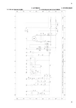
Page 28: ...28 28 9 APPENDIX 9 9 3 Circuit diagram 220V 9 3 220...

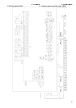
Page 29: ...29 9 APPENDIX 9 9 4 Wiring diagram 220V 9 4 220...

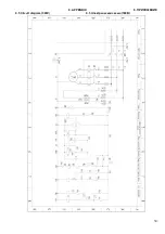
Page 30: ...30 9 APPENDIX 9 9 5 Circuit diagram 380V 9 5 380...

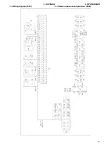
Page 31: ...31 9 APPENDIX 9 9 6 Wiring diagram 380V 9 6 380...

Reviews: