background image

14

Before You Begin

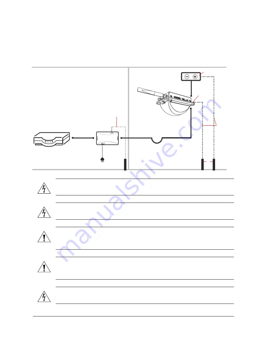
Become Familiar with the Installation Components

Figure 10.

Typical installation components using both PoE and DC power sources 

WARNING:  

Only trained and qualified personnel should be allowed to install, replace, 

or service this equipment.

WARNING:  

Installation of this equipment must comply with local and national electrical 

codes.

CAUTION:  

Make sure that you form a 3”-5” drip loop in any cable that is attached to the 

Access Point. This will prevent water from running along the cable and entering the Access 
Point or the building where the cable terminates.

CAUTION:  

Be sure that grounding is available and that it meets local and national 

electrical codes. For additional lightning protection, use lightning rods and lightning 
arrestors.

.

WARNING:  

The Ruckus Wireless PoE injector (if supplied with your Access Point) is for 

indoor use only. Never mount the PoE injector outdoor with the Access Point.

INDOOR

OUTDOOR

DC power source

Router or switch

PoE injector

ZoneFlex 7762-T 

Outdoor AP

CA

T5 Etherne

ca

ble

Po

E

 p

o

w

e

ad

ap

te

r

Outdoor

-ra

te

C

at5e FT

P ca

ble

D

ri

p

 loop

O

u

tdoo

r-

ra

ted 

Ca

t5e

 FTP ca

ble

DC c

able

Gr

o

und r

o

ds

Ground 

screw

18 AWG min 

green-and-

yellow wire 

used

18 AWG min 

green-and-

yellow wire 

used

Gr

o

und r

o

d

Summary of Contents for ZoneFlex 7762-T

Page 1: ...Ruckus Wireless 7762 T Dual Band 802 11n Outdoor Access Point Installation Guide Part Number 800 70318 001 Published April 2011 www ruckuswireless com...

Page 2: ......

Page 3: ...gement by ZoneDirector 15 What You Will Need 15 Step 1 Connect the Cables to the Access Point 16 Step 2 Connect the Access Point to the Same Subnet as ZoneDirector 20 Step 3 Disconnect the Access Poin...

Page 4: ...cket to the Mounting Surface 42 Attaching the Bracket to a Flat Surface 42 Attaching the Bracket to a Pole 45 Step 2 Attach the Dynamic Bracket to the Access Point 47 8 Mounting the Access Point 48 9...

Page 5: ...eless com documents Release Notes Provides late breaking information about the current software release including new features enhancements and known issues If the information in the Release Notes dif...

Page 6: ...c bag containing the Ruckus Wireless PoE injector for ZoneFlex 7762 T AP Box containing the power adapter for the PoE injector Box containing the mounting kit see Mounting Kit Contents for details Sma...

Page 7: ...nts Figure 1 DC connector pins and DC cord connector assembly Figure 2 RJ 45 waterproofing assembly Boot DC cord connector Coupling ring Connector pins 4 pieces Cable clamp housing RJ 45 connector on...

Page 8: ...et Static bracket Steel clamp 2 pieces Machine screws 8 pieces Hex bolts 4 pieces Flat washers 4 pieces Split lock washers 4 pieces Wall anchors 4 pieces Figure 4 Mounting kit contents Dynamic bracket...

Page 9: ...y the following tools and equipment A notebook computer running Windows 2000 XP Vista 7 with one wireless 802 11b g n network card and one Ethernet card installed A pair of long nose pliers 6mm flathe...

Page 10: ...features that are relevant to the installation and mounting instructions that this guide provides Before you begin the installation process Ruckus Wireless recommends that you become familiar with th...

Page 11: ...abled but the WLAN service is available the Status LED is also green Fast flashing green The AP is part of a mesh network as Mesh AP and is connected to an uplink with fair signal Slow flashing green...

Page 12: ...refer to Optional Mounting and Connecting the 5GHz External Antennas on page 51 NOTE The maximum value for the antenna gain that you should set depends on the type of external antennas that you are c...

Page 13: ...s The maximum radio range is achieved at the lowest workable data rate Higher data rates will generally be achieved at closer distances Antenna type and placement Proper antenna configuration is a cri...

Page 14: ...ignals Building materials used in construction also influence radio signal penetration For example drywall construction permits greater range than concrete blocks For more Access Point placement guide...

Page 15: ...Before You Begin Determine the Optimal Mounting Location and Orientation Figure 7 Recommended orientation for maximum horizontal plane coverage Limited Reach Excellent Reach Excellent Reach Good Reac...

Page 16: ...2 Before You Begin Determine the Optimal Mounting Location and Orientation Figure 8 Recommended orientation for maximum vertical plane coverage Limited Reach Excellent Reach Excellent Reach Good Reach...

Page 17: ...erhang of a building or a streetlight pole Refer to Figure 10 for the components involved in a typical installation Take note of the components that must be installed indoor and outdoor The PoE inject...

Page 18: ...the Access Point or the building where the cable terminates CAUTION Be sure that grounding is available and that it meets local and national electrical codes For additional lightning protection use li...

Page 19: ...stalled on the network you can configure the Access Point for management by ZoneDirector Simply connect the Access Point to same Layer 2 subnet as ZoneDirector When the Access Point starts up it will...

Page 20: ...er source at this point even if you are planning to use both PoE and DC power in your final deployment Use Power Over Ethernet 1 Take out the PoE injector and the power adapter from the Access Point p...

Page 21: ...ctor on the AP To complete this task you will need A 0 195 to 0 265 diameter DC cable that is long enough to connect the AP at its mounting location with the DC power source A pair of long nose pliers...

Page 22: ...four conductors 4 Insert the stripped part of the conductors into the four connector pins and then crimp the edges of the connector pins to secure the conductors Alternatively use a soldering gun to...

Page 23: ...to the connector body The two clamps should snap into their compartments 8 Push the boot all the way forward so that it covers the cable clamp housing securely 9 Remove the protective cap from the 12V...

Page 24: ...address This allows the Access Point to register with ZoneDi rector When the Status column shows Connected this indicates that the Access Point has successfully registered with ZoneDirector and that i...

Page 25: ...dify the computer s IP address settings 1 On your Windows XP or Windows 2000 computer open the Network Connections or Network and Dial up Connections control panel according to how the Start menu is s...

Page 26: ...close the TCP IP Properties dialog box 7 Click OK again to close the Local Area Connection Properties dialog box Windows saves the IP address settings that you have configured Figure 16 Sample config...

Page 27: ...package 2 Obtain two Cat5e or better Ethernet cables 3 Connect one end of one Ethernet cable to the AP BRIDGE port on the PoE injector and then connect the other end to the PoE IN port on the Access P...

Page 28: ...o connect the AP at its mounting location with the DC power source A pair of long nose pliers A soldering gun optional To assemble the DC cord connector and supply DC power to the AP 1 Connect one end...

Page 29: ...nector pins and then crimp the edges of the connector pins to secure the conductors Alternatively use a soldering gun to solder the conductors to the pins 6 Insert all four connector pins into the hol...

Page 30: ...rom the 12V DC connector on the AP 11 Connect the DC cord connector that you have assembled to the 12V DC connector on the AP 12 Connect the DC cable to a DC power source for example a battery You hav...

Page 31: ...plete this step you will need to configure the settings on the Common tab and at least one Wireless tab These are the essential wireless settings that will enable wireless devices on the network to as...

Page 32: ...cryption security Disabled on all WLANs Default management IP address 192 168 0 1 Table 4 Common wireless configuration Setting Recommended Value Wireless Mode Auto select Channel SmartSelect Channel...

Page 33: ...descriptive name that you want to call this wireless network For example you can type Ruckus Wireless AP This SSID is the name that will help users identify this wireless network in their wireless net...

Page 34: ...an also use DHCP Option 43 or DNS to point the Access Point to the FlexMaster server For more information refer to the FlexMaster User Guide 1 On the menu click Administration Management 2 Scroll down...

Page 35: ...r 7762 T AP and power adapter to supply power to the AP you can use PoE OUT port to supply PoE to any PoE capable device for example another ZoneFlex 7762 T AP or an IP based surveillance camera The P...

Page 36: ...that some features specifically the built in heater and PoE for the PoE OUT port will be unavailable if the supplied PoE injector is not used Refer to Table 5 for the available power options and the l...

Page 37: ...then click Properties 3 When the Local Area Connection Properties dialog box appears select Internet Protocol TCP IP from the scrolling list and then click Properties The TCP IP Properties dialog box...

Page 38: ...y that the Access Point is operating normally If the Access Point is operating normally and no wireless clients are associated with it The Power LED is green The Status LED shows slow blinking amber T...

Page 39: ...Point from the Network 1 Disconnect the Access Point from the power source 2 Disconnect the Ethernet cable that runs to the Access Point s RJ45 port from your network s router or switch You are now re...

Page 40: ...ame procedure You have completed connecting the RJ 45 cable and sealing the connection Step 2 Complete the Power Connections The Access Point supports both PoE and DC power and it can be connected to...

Page 41: ...t and then connect the other end to the AP BRIDGE port on the PoE injector 4 Connect one end of the other Ethernet cable to the NETWORK port on the PoE injector and then connect the other end to your...

Page 42: ...pair of long nose pliers A soldering gun optional To assemble the DC cord connector and supply DC power to the AP 1 Connect one end of an Ethernet cable to the PoE IN port on the AP and then connect t...

Page 43: ...then crimp the edges of the connector pins to secure the conductors Alternatively use a soldering gun to solder the conductors to the pins 6 Insert all four connector pins into the holes on the cord c...

Page 44: ...DC cable to a DC power source for example a battery You have completed connecting the Access Point to the administrative computer and to a DC power source WARNING Do not apply power to the Access Poi...

Page 45: ...the PoE IN port on the AP is connected to the AP BRIDGE port on the PoE injector 5 Connect the Ethernet cable from the NETWORK port on PoE injector to your network router or switch 6 Apply power to th...

Page 46: ...le Two steel clamps supplied with the AP 10mm flathead screwdriver Step 1 Attach the Static Bracket to the Mounting Surface The procedure for attaching the bracket to the mounting surface depends on w...

Page 47: ...ations of the mounting holes o 3 Remove the static bracket from the mounting surface 4 Drill an 8mm diameter hole with a depth of 36mm 38mm into each of the four markings that you made on the mounting...

Page 48: ...racket with the flat washers and the hex nuts 9 Using a 10mm open end wrench tighten the nuts to secure the bracket to the mounting surface Screw torque value must be 0 4 0 5 Newton meter Nm As you ti...

Page 49: ...Access Point can be mounted vertically or horizontally on a 30mm to 60mm 1 18 in to 2 36 in pole 1 Insert the open end of one steel clamp into the upper two tabs on the bracket 2 Take the other steel...

Page 50: ...6 Attaching the Mounting Brackets Step 1 Attach the Static Bracket to the Mounting Surface 3 Use the clamps to attach the bracket to the pole Figure 37 Use the clamps to attach the bracket to the pole...

Page 51: ...cket 5 Continue to Step 2 Attach the Dynamic Bracket to the Access Point Step 2 Attach the Dynamic Bracket to the Access Point 1 Place the dynamic bracket onto the flat side of the Access Point so tha...

Page 52: ...oint you will need to join the two mounting brackets that you attached earlier to the device and the mounting surface For this procedure you will need the following items Hex bolts 10mm ratchet wrench...

Page 53: ...not create any signal interference for the antenna Figure 39 Joining the two brackets in a vertical pole installation 2 Align the mounting holes on the dynamic bracket with the mounting holes on the s...

Page 54: ...esired orientation NOTE If you have not yet determined the optimal orientation for your Access Point refer to Determine the Optimal Mounting Location and Orientation on page 10 for orienta tion guidel...

Page 55: ...e in case you need them later 3 Connect the 5GHz antennas to the standard N type female antenna connectors on the Access Point If the 5GHz antennas come with RF coaxial cables for example a patch ante...

Page 56: ...in to the 7762 T AP via the command line interface 2 Set the 5GHz antenna gain by entering the following command set extantgain wifi name 0 90dBi 3 Verify that the antenna gain has been configured by...

Page 57: ...from the ZoneDirector Web interface Figure 41 Configure the external antenna gain 10 Resetting the Access Point to Factory Default Settings You can reset the Access Point to its factory default setti...

Page 58: ...54 Resetting the Access Point to Factory Default Settings Configuring the 5GHz Antenna Gain Figure 42 Note the location of pins 3 and 4 Pin 4 Pin 3...

Page 59: ...55 Resetting the Access Point to Factory Default Settings Configuring the 5GHz Antenna Gain 4 Install the shunt on pins 3 and 4 as shown in Figure 43 Figure 43 Install the shunt Pin 3 Pin 4...

Page 60: ...56 Resetting the Access Point to Factory Default Settings Configuring the 5GHz Antenna Gain 5 Wait 10 seconds and then remove the shunt Figure 44 Wait 10 seconds Figure 45 Remove the shunt...

Page 61: ...rs from logging in to the Access Point s Web interface and changing the access point settings to compromise your network Configure the Security Settings Unlike wired networks anyone with a compatible...

Page 62: ...58 What to Do Next Read Related Documentation...

Reviews: