F
Frro
on
ntt
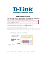
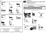
1. Power (PWR) LED
When this green LED is on, the router is powered up.
2. DSL LED
This green LED flashes while a link is being set up on the ADSL port. The
LED stays on when the link has been set up and is functioning correctly.
3. Online LED
This green LED will normally be off but flashes when data is sent or
received on the ADSL port.
4. WLAN LED
When this green LED is on, wireless networking is enabled. The LED will
flash when data is sent or received over a wireless connection.
5. LAN LEDs (LAN1, LAN2, LAN3 and LAN4)
These green LEDs turn on when there is an Ethernet connection to the
corresponding LAN port on the back panel (see 10 below) and will flash to
indicate that data is being sent or received over the connection.
B
Ba
ac
ck
k
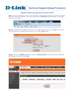
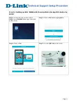
6. ADSL Port
Use the supplied cable to connect the ADSL port to your phone socket. The
DSL LED on the front panel will light up when the connection is made (see
2 above) and the Online LED (see 3) will turn when you are able to send and
receive data.
7. Power
Connect the supplied, 12V power adapter to this socket.
8. Reset
You can restart the unit by pressing the reset button and releasing it
immediately. If, for any reason, you need to reset the unit to factory
defaults and cannot access the user interface (e.g. if you have changed and
forgotten the password), press the reset button for 10 seconds. Note that
you will lose all your configuration changes when you reset the router to
factory defaults. You may have to use a thin implement, like a straightened
paper-clip, to reach the switch.
9. On/Off Switch
When the power adapter is connected (see 7 above) and this switch is
pressed in, your router will power up.
10. LAN Ports (1, 2, 3 and 4)
There are four Ethernet LAN ports for connection to PCs, network printers
or similar devices. Note the labelling; one LAN LED on the front panel is
associated with one port on the rear panel. Port 1 is associated with the
LAN1 LED, port 2 with LAN2 and so on. If a device is not correctly connected,
using a suitable Ethernet cable, the associated LED will not turn on.
•
An ADSL line installed by your ISP
•
An ADSL splitter (at least one)
•
A Computer with a CD-ROM drive and working Ethernet port
•
Windows (98 or later), MacOS (9.x or later) or Linux
•
An up to date web browser:
•
Internet Explorer 5.5 or later
•
Mozilla 1.7/Firefox 1.0 or later
Package Contents
Package Contents
Hardware Description
Hardware Description
After unpacking the SMC7904WBRA, check the contents of the box to be
sure you have received the following components:
•
One Barricade™ g Wireless Broadband Router
•
One Power Adaptor
•
One cable (RJ-11) for connection to the phone line
•
One cable (RJ-45) for optional connection to a LAN device
•
One CD-ROM containing full version of User Manual
•
One Warranty Card
•
One ADSL splitter *
* The ADSL splitter (also called microfilter) is only contained in packages
related to specific countries (US, UK, France, The Netherlands). If your
package does not contain a splitter, you may be required to purchase
this item separately. Please contact your ISP for further details.
Please inform your dealer in the event of any incorrect, missing or damaged
parts. If possible, retain the carton and original packing materials in case
there is a need to return the product.
System Requirements
System Requirements
FOR TECHNICAL SUPPORT, CALL:
From U.S.A. and Canada:
(24 hours a day, 7 days a week)
(800) SMC-4-YOU - Phn: (949) 679-8000 -
Fax: (949) 679-1481
From Europe:
Contact details can be found on www.smc.com.
INTERNET
E-mail addresses:
[email protected]
[email protected]
Driver updates:
Please go to the SUPPORT section on
www.smc.com and enter the DOWNLOADS pages.
World Wide Web:
http://www.smc.com
If you are looking for further contact
information, please visit www.smc.com.
38 Tesla
Irvine, CA 92618
Phone: (949) 679-8000
Model Number: SMC7904WBRA
Troubleshooting
Troubleshooting
IIn
nsstta
alllla
attiio
on
n T
Trro
ou
ub
blle
essh
ho
oo
ottiin
ng
g
• Check that the Power Adapter is both plugged into a working power socket
and connected to the Router. Check that the On/Off switch on the back of
the Router is pressed in and that the green PWR LED on the Router is
turned on. Only use the power adapter that was supplied with your Router.
• The wired PC should connect to a LAN port of the Router using an Ethernet
cable. The corresponding LAN LED of the Router should be on.
• The Router ADSL port should be connected to your phone socket on the wall.
The DSL LED should be on when there is a valid connection to your ISP. The
Online LED will flash when data is transferred to and from the ADSL port.
• Power up your equipment in the following order: First the ADSL Router and
then your PC. Leave at least 30 seconds between turning on each device.
• The PC should be setup to obtain an IP address automatically from the
Router's DHCP server. See the user manual on the CD for details of how to
setup your PC to obtain an IP address.
• Check that web proxy is disabled on your PC. Go to the
Control Panel and
select
Internet Options. Select the Connections tab and click the LAN
Settings button. Check that the Use Proxy Server option is not ticked.
• Check you can access the Router's web interface. Open a browser and enter
h
httttp
p::////119
92
2..116
68
8..2
2..11 to access the default IP address of the Router.
W
WA
AN
N C
Co
on
nn
ne
ec
cttiio
on
n T
Trro
ou
ub
blle
essh
ho
oo
ottiin
ng
g
• Check that you have selected the correct WAN connection option and the
ISP details are correct. If you do not have these details, they can be
obtained from your ISP.
• If you have any PPPoE client applications already installed on your PC which
were required when your PC was directly connected to the DSL modem,
they must be disabled.
W
Wiirre
elle
essss T
Trro
ou
ub
blle
essh
ho
oo
ottiin
ng
g
• Check that the SSID is the same on the Router and the wireless PC.
• Check that the wireless encryption is the same on the Router and the
wireless PC. To help debug a problem, turn off encryption in both the Router
and wireless PC until you can establish a connection. After a change in
encryption, some PCs may have to be restarted.
• The wireless PCs must be set to Infrastructure mode to work with a Router.
• If your computer has both a wired and wireless connection installed, ensure
that the wired Ethernet cable is unplugged.
• Check that the Router WLAN LED is on, to indicate that Wireless networking
is enabled. To enable wireless networking, go to the Router Wireless page
and enable Wireless Networking.
• If there are a number of wireless networks within range, then you may
experience poor wireless performance if the wireless channels are too close
together. Ideally, neighbouring wireless networks should be at least 5
channels apart. The wireless channel is controlled by and set in the Router.
• The Router has a feature called
MAC Filter which controls which wireless PCs
have access to the wireless LAN. If this feature is enabled, then ensure that
the MAC address of your wireless PC card is listed in the
MAC Filter page.
C
Co
om
mp
plliia
an
nc
ce
e a
an
nd
d W
Wa
arrrra
an
ntty
y
• Details regarding compliance and warranty can be found on the user manual
located on the CD-ROM
E
Etth
he
errn
ne
ett c
ca
ab
blle
ess
Ethernet cables are usually constructed from unscreened, “Cat 5” cable with
RJ45 connecters at both ends. Cables of this type can be purchased at most
computer retailers.
SMC7904WBRA.qxd 19/01/05 17:31 Page 1