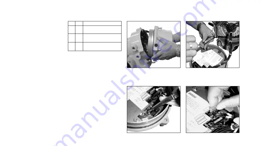
4
houses the battery pack and
charging/control circuitry and care
must be taken that it does not drop.
Ensure the two 20A fuses located in
a plastic bag are kept safely - DO
NOT FIT
The cover is restrained with an
external chain to support its weight
(5.5 Kg approx) and prevent
interconnecting cables being damaged.
The battery failsafe cover assembly
is supported by the restraining chain
during commissioning.
2. Set control Links.
Figure 4
Referring to the label, locate PCB
links LK1 and LK2. Links determine
required action on loss of AC supply
to the actuator.
Using pliers, fit links LK1 and LK2 in
required positions.
Links bridge between pins 1-2 or 2-
3 and must be set for the desired
action as detailed in table the below:
*The direction required for
failsafe operation and ESD
contact form (if being used) is
set with the IQT setting tool.
Refer to 6, page 4.
LK1 LK2 Required action
1-2 1-2 Failsafe on loss of supply,
ESD [A2] set [NO]*
2-3 1-2 Failsafe on loss of supply,
ESD [A2] set [NC]*
1-2 2-3 Stayput waiting for
command (30 Min max)
3. Connect ESD/Interlock
control wiring.
Figure 5
If the control of the IQT actuator
with AC supply switched ON
requires emergency shut down
and/or interlocks, ESD and/or
interlock field wiring must be
connected to the green terminal
plug located on the battery pack
assembly.
If ESD and/or interlocks do not form
part of the IQT control scheme then
no wiring is necessary.
Remove plug by pulling it straight
up and connect field wiring for ESD
and/or interlocks as indicated on the
label and actuator wiring diagram.
Once connected, re-fit the wired
plug into its socket. The plug and
socket are polarised, ensuring they
cannot be mated incorrectly.
Fig. 3
Fig. 4
Fig. 5
Fig. 6


