13
Das Kabel wird im Arbeitsraum der Werkzeug-
maschine durch den Schutzschlauch oder das
Schutzrohr gezogen. Durch diesen Schutz-
schlauch wird Luft nach innen zum Gerät ge-
führt. Die Sperrluft verhindert das Eindringen
von Kühlmittel. Die Sperrluft muss grundsätzlich
angeschlossen sein. Durch unterschiedliche Di-
mensionen der Leitungen muss der Einstell-
druck individuell angepasst werden. Abb. 6.2
The cable passes through the working area by a
protective hose or a rigid tube.
By the protective
tube air is supplied to the device. The sealing air
prevents the ingress of coolant. The sealing air
must be connected fundamentally. Due to dif-
ferent dimensions and lengths of cables, the
static pressure in the unit should be adjusted in-
dividually.
Fig. 6.2
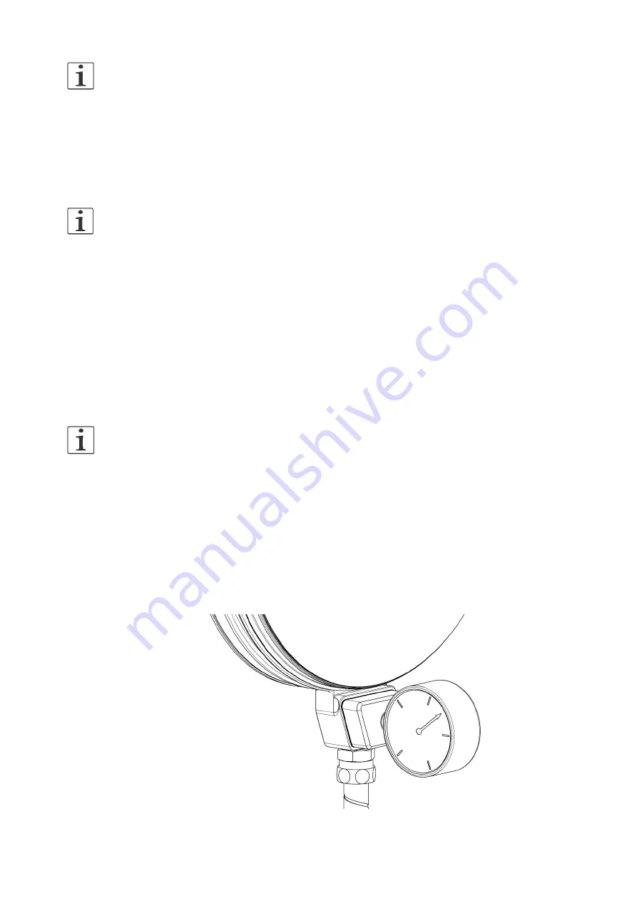
Zum sicheren Betrieb des Gerätes ist ein Stau-
druck von 2-5mbar (200-500Pa) in der An-
schlussbox erforderlich. Nur so ist das Gerät
dicht. Einen entsprechenden Adapter bieten wir
als Zubehör an. Abb. 6.1
Der Staudruck darf 2bar nicht übersteigen.
For reasons of safe operation and reliable leak
tightness a static pressure of 2-5mbar (200-
500Pa) in the connecting box is necessary. We
offer an appropriate adapter as accessory part.
Fig. 6.1
Ram pressure not exceed than 2bar
Prüfen Sie den Staudruck in der Box. Benutzen
Sie dazu einen Adapter mit Manometer (Zube-
hör). Drücken Sie den Adapter auf die offene
Anschlussbox.
Verändern Sie den Einspeisedruck bis Sie min-
destens einen Staudruck von 2mbar (200Pa) er-
reicht haben.
Check the static pressure in the box. Use an
adapter with a manometer (accessory).
Press adapter onto the open connecting box.
Adjust the feed pressure until the dynamic pres-
sure of 2 mbar (200Pa) is reached.
Je nach Einbausituation kann es sinnvoll sein,
ein starres Schutzrohr Ø 12x1 mit nachfolgen-
dem Kabelschlepp zu verlegen. Abb. 6.3
Wenn die Dimensionen und Längen nach Abb.
6.2 und 6.3 eingehalten werden, kann der Ein-
speisedruck auf ca. 0,5 bar eingestellt werden.
In Abhängigkeit vom Abstand zwischen Einspei-
sung und Rotoclear kann der Druck von 0,3 bis
2 bar notwendig sein um einen Durchfluss von
mindestens 1,2 Nm³/h zu erreichen. Eine ge-
naue Einstellung (Abb. 6.1) reduziert den Luft-
verbrauch.
Depending on the situation of installation it may
be necessary to install a rigid protective tube
Ø 12x1 with cable track. Fig 6.3
If the dimensions and lengths executed accord-
ing to fig. 6.2 and 6.3, you can set the feed-in
pressure to approx. 0.5 bar. Depending on the
distance between source and Rotoclear, the
feed pressure of 0.3 to 2bar to be necessary in
order to obtain the sealing air of at least 1.2
m³/h. An accurate adjustment (Fig. 6.1) will re-
duce the air consumption.
Abb./ Fig. 6.1
Summary of Contents for P-11500
Page 14: ...14 Abb Fig 6 2 Abb Fig 6 3...


