


User Interface
R&S
®
GP-U/GP-E/GP-S/GP-T
54
User Manual 3646.3836.02 ─ 01
Chapter 3.2, "Icons and Buttons"
Ethernet Interfaces Settings
Under "Network > Interfaces > Ethernet Interfaces", you can display more detailed
information on the available Ethernet interfaces and adjust the settings.
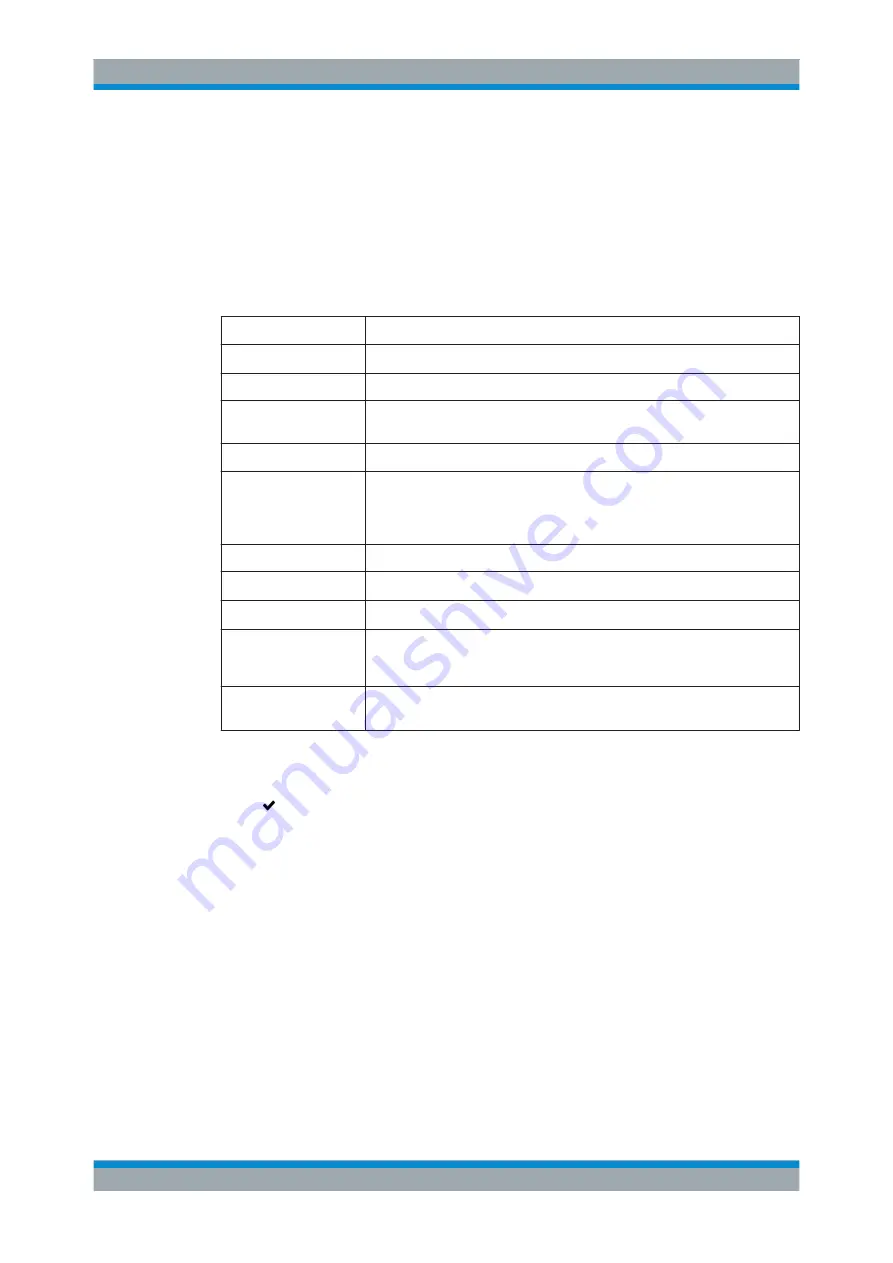
The "Ethernet Interface" panel displays the following information and allows you to
configure the following elements:
Field
Description
"Name"
Displays the name of the Ethernet interface, e.g.
eth0
.
"Description"
Displays a short description of the Ethernet interface.
"Hardware Address"
Displays the hardware address (Ethernet MAC address) of the Ethernet inter-
face.
"Used by"
Displays the connection that is currently using the Ethernet interface.
"Status"
Displays the status of the Ethernet interface.
The status can be one of the following:
●
up
– The Ethernet interface is enabled.
●
disabled
– The Ethernet interface is disabled.
"Speed"
Displays the speed (e.g. in Gbit/s) of the Ethernet interface.
"Duplex"
Displays the duplex mode of the interface, e.g.
full
.
"Type"
Displays the type of wiring connected to the interface, e.g.
twisted pair
.
"ON"/"OFF"
A slider switch indicates whether the Ethernet interface link is active ("ON") or
inactive ("OFF"). By clicking the slider switch, you can toggle the state of the
Ethernet interface link.
"MTU"
Set the maximum size of each packet (in bytes). The Maximum Transmission
Unit can be any integer from
64
to
16384
.
If you modify the settings, click "Save" to store your changes or "Reset" to discard
them. Otherwise, click "Close" to shut the editor panel.
Click " Activate" in the toolbar at the top of the desktop to apply your configuration
changes.
VLAN Interfaces
Use the "VLAN Interfaces" settings to add custom Virtual Local Area Network tags to
all traffic on a given interface.
This method can be used to create »virtual interfaces« that allow you to put several
logical network zones on one physical interface. When a VLAN tag is associated with a
network interface, the tag is added to all outgoing packets that are sent via this virtual
interface and stripped from the incoming packets that are received on this VLAN. Sev-
eral VLANs may be associated with each network interface. Packets with different tags
can be processed and associated to the corresponding interface.
For more detailed information on VLAN interfaces, see the following sections.
Menu Reference


