background image

27

Chapter 1 - Getting Started

1-5 Switching On the Power for the First Time

Step 1: Install Ink Cartridges

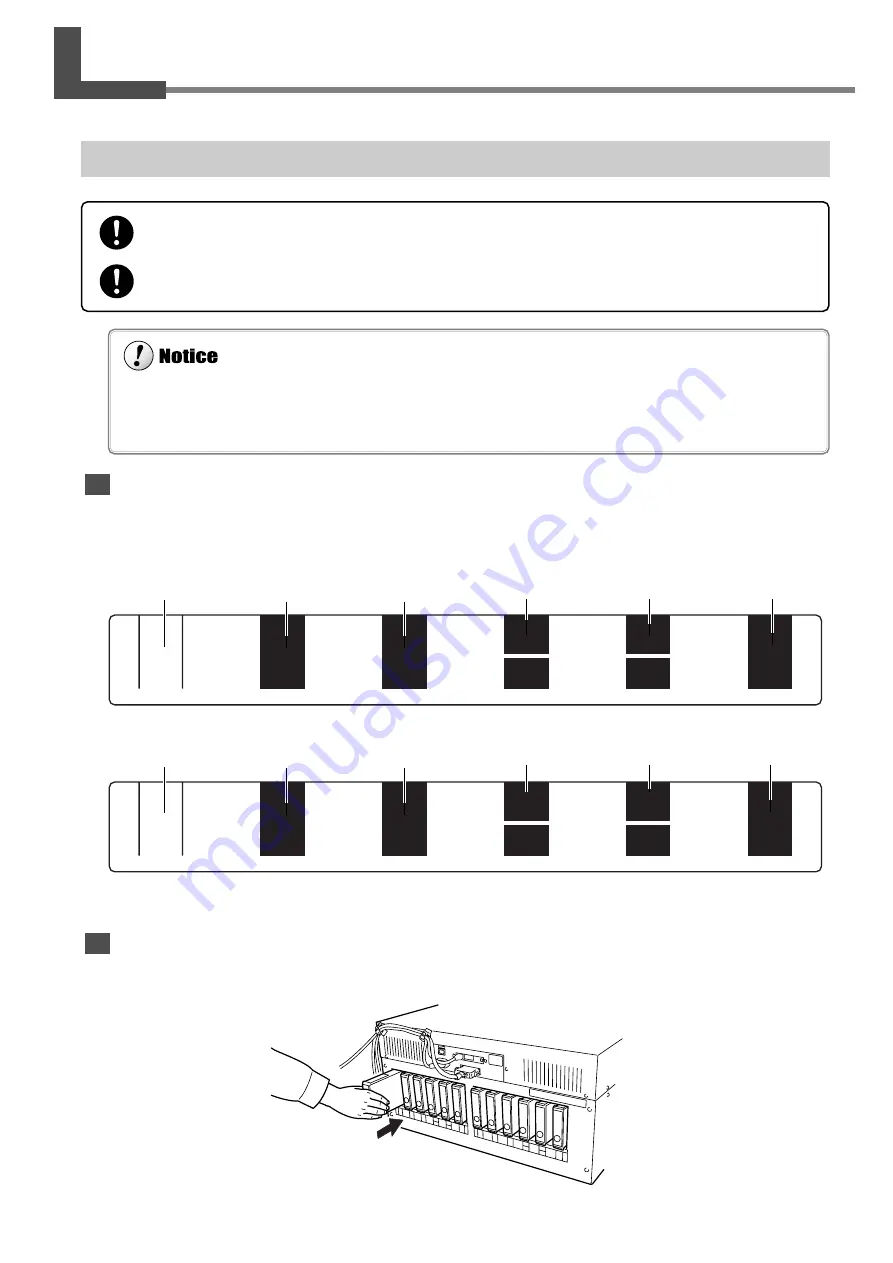
Confirming the Ink-insertion Sites

Before you insert a cartridge, be sure to examine the label on the ink-cartridge port and make sure the ink color matches
the slot where it is to be inserted. Insert the same type and color of ink-cartridge into 1 through 6 and 7 through 12.

Installing Ink Cartridges

Insert each ink cartridge into the corresponding ink-cartridge port. Insert it firmly, as far as it will go.

1

2

3

4

5

6

7

8

9

10

12

11

BK

BK

CY

MG

LC

OR

GR

LM

YE

CY

MG

LC

OR

GR

LM

YE

If an ink cartridge is dropped, the shock due to the fall may damage the ink cartridge and make it unusable.

Be sure to use genuine pigment or dye-based ink cartridges from Roland DG Corp. Installing other types of ink cartridges may
result in incorrect color blending when printing or may cause malfunction.

Black                       Cyan                    Magenta                                                                                   Yellow

Black                       Cyan                    Magenta                                                                                  Yellow

Light cyan            Light magenta
      or                             or
  Orange                     Green

Light cyan            Light magenta
      or                             or
  Orange                     Green

Store ink cartridges out of the reach of children.

If ink contacts the eyes, flush immediately with water.

Summary of Contents for Hi-Fi Jet Pro II FJ-540

Page 1: ...fications of this product are subject to change without notice The operation manual and the product have been prepared and tested as much as possible If you find any misprint or error please inform us...

Page 2: ...gulations CLASSE A AVIS Cet appareil num rique de la classe A respecte toutes les exigences du R glement sur le mat riel brouilleur du Canada WARNING This is a Class A product In a domestic environmen...

Page 3: ...Protective Media 23 1 4 Connecting the Cables 24 Connecting the Power Cord 24 Connecting to the Computer 25 1 5 Switching On the Power for the First Time 27 Step 1 Install Ink Cartridges 27 Step 2 Pe...

Page 4: ...parent Media 52 3 6 Making Corrections for Printing 53 Feed Correction 53 Bidirectional Correction 54 3 7 Stopping Printing Operations 57 Stopping Printing Operations 57 Pausing Printing Operations 57...

Page 5: ...83 6 1 What to Do If 84 The Machine Doesn t Run 84 Clean Attractive Printing Is Impossible 85 The Media Becomes Jammed 88 What to Do If the Printing Carriage Does Not Operate 89 6 2 What to Do If an E...

Page 6: ...chine has a built in print server Roland PrintServer as a network interface When you use the print server you can send printing data to the machine from anywhere on the network Includes a Software Ras...

Page 7: ...gs that must be carried out The specific thing that must be done is indicated by the design contained within the circle The symbol at left means the power cord plug must be unplugged from the outlet A...

Page 8: ...hands Doing so may result in electrical shock To Ensure Safe Use When not in use for extended periods unplug the power cord from the elec trical outlet Failure to do so may result in danger of shock e...

Page 9: ...ng knife with your fingers Doing so may result in injury Do not touch the control panel while head cleaning or other cleaning is in progress The printing carriage may move and cause injury To Ensure S...

Page 10: ...of this product The following figure describes the location and content of these messages To Ensure Safe Use Rating label Use a rated power supply Do not place hands within the space to the front of t...

Page 11: ...cercle Le symbole gauche signifie que le fil lectrique doit tre d branch de la prise propos des symboles Ne pas d monter r parer ni modifier D monter r parer ou modifier l appareil ris que de provoque...

Page 12: ...Ne pas le plier le tordre l tirer l attacher ou le serrer de fa on excessive Ne pas placer d objet ou de poids sur le fil N gliger de suivre cette consigne peut endommager le fil lectrique ce qui risq...

Page 13: ...e pas toucher le bout de la lame s paratrice avec les doigts Une n gligence ce niveau pourrait provoquer des blessures Ne pas toucher le panneau de commande pendant le nettoyage des t tes ou d autres...

Page 14: ...ion appropri e Ne pas mettre les mains dans l espace devant l l ment quand celui ci est en marche Ne pas d monter la cartouche Conserver hors de la port e des enfants Ne pas emmagasiner das temp ratur...

Page 15: ...13 1 Getting Started This section describes what to do when you first open the packing carton including installing the machine and connecting it to a com puter...

Page 16: ...ft 1 Bolts Large 16 Bolts Small 14 Washers 6 Hexagonal wrench 1 Pipe 1 Media flanges 2 Flange retaining pins 2 Drain bottle 1 Software RIP 1 User s manual 1 Replacement blade for separating knife 1 Ro...

Page 17: ...Started POWER 1 2 Part Names Front View Front cover Sheet loading lever Cover Operation panel Cover Ink cartridge ports Drain bottle RJ 45 Ethernet connector Main power switch Rear View Power connecto...

Page 18: ...e Inside the Front Cover Media clamp Display TEST PRINT key SETUP key CLEANING key SHEET CUT key MENU key ENTER key PAUSE key PAUSE LED BASE POINT key BASE POINT LED POWER key SETUP LED Operation Pane...

Page 19: ...cing the unit on the stand Doing so may result in injury Use the joining bolts to secure the unit to the stand Failure to do so may result in falling of the unit leading to injury Never install the un...

Page 20: ...d legs with your hand attach the left and right hand casters 2 Set the stand upright so that the casters are at the bottom and place the machine on the stand The front and rear of the stand are as sho...

Page 21: ...19 Chapter 1 Getting Started 1 3 Assembling and Installing 3 Use the included large bolts to secure the machine to the stand Three places each on the left and right Washer Bolt Large...

Page 22: ...nd secure in place with the flange retaining pins Media guide Front Short Long Rear Bolts Small Right hand side of the back of the unit Left hand side of the back of the unit Flange retaining pins 2 M...

Page 23: ...nsert the drain tube securely into the bottle stand Leave the drain bottle attached at all times removing it only when moving the machine or disposing of collected ink When you remove the stopper from...

Page 24: ...ation about how to dispose of discharged ink 4 5 Disposing of Discharged Ink When the level of collected fluid is in this range detach the drain bottle and dispose of the discharged ink Drain bottle B...

Page 25: ...lling the machine remove all protective media Front 2 Peel off the tape 4 Remove the retainer 1 6 Peel off the tape 5 Remove the retainer 2 3 Peel off the tape and remove the packing Pull straight bac...

Page 26: ...the unit are switched off Arrange the power cord and interface connection cable to prevent tripping when moving around the unit Use only with a power supply of the same rating as indicated on the uni...

Page 27: ...Connection to a Parallel Connector When making the connection to the computer using a printer cable connect the printer cable at the position shown in the figure Cables are available separately One w...

Page 28: ...ring the Cable Pass the cable through the established location making sure that it does not touch the loaded media If the cable touches the media during printing media feed may be obstructed resulting...

Page 29: ...port Insert it firmly as far as it will go 1 2 3 4 5 6 7 8 9 10 12 11 BK BK CY MG LC OR GR LM YE CY MG LC OR GR LM YE If an ink cartridge is dropped the shock due to the fall may damage the ink cartr...

Page 30: ...POWER key on the operation panel 3 Make sure the cartridges are installed into the ink cartridge ports Select the installed ink type and press the EN TER key 4 Follow the messages to make sure the dra...

Page 31: ...29 2 Basic Operation This describes the sequence of basic operations from switching on the power to performing printing...

Page 32: ...ver the platen If the machine is allow to stand to with the printing heads uncapped for a pro longed period the printing heads may become irreversibly clogged Before switching off the main power be su...

Page 33: ...tching Off the Power at the End of the Day Press and hold down the POWER key for one second or longer to switch off the sub power The POWER LED goes out Leave the pinch rollers raised when not in use...

Page 34: ...install the media guide when loading roll media Otherwise the roll may fall and cause injury Load roll media at the proper position Otherwise the roll may fall resulting in injury 1 2 3 4 2 in 3 in Li...

Page 35: ...e media clamps to the two ends of the platen 6 Pass the end of the media from the back of the machine to the front Pull out the media until the sensor is hidden from view 7 Grasp the center of the end...

Page 36: ...4 mm Top menu The SETUP LED lights up When the machine will remain unused for an extended period remove roll media from the machine and store it If roll media is left mounted on the machine for an ext...

Page 37: ...with the guide line Rear View Remove the left hand media flange at the back of the unit Move the right hand media flange at the back of the unit to a position where it does not touch the loaded media...

Page 38: ...changes When the lever is moved to position 1 low One beep When the lever is moved to position 2 middle Two beeps When the lever is moved to position 3 high Three beeps 5 Close the front cover The pr...

Page 39: ...se from the media clamps After about 1 m 3 ft of media has been fed check the positioning of the media clamps If the media looks like it may come loose from the media clamps adjust the positioning of...

Page 40: ...UP LED is lighted hold down the SETUP key for at least one second 3 Move the sheet loading lever toward the back of the unit The pinch rollers rise to release the media 4 Remove the media Depending on...

Page 41: ...dia to rub against the heads which may result in a paper jam or damage to the heads The printing heads may be left uncapped that is the printing carriage may remain over the platen If the machine is a...

Page 42: ...out a printing test The test pattern is printed 2 If dot drop out is present clean the heads For more information about head cleaning see 4 1 Cleaning the Printing Heads Downloading Printing Data Pri...

Page 43: ...41 3 A Wide Variety of Operations This section describes a wide variety of operations and functions grouped by task...

Page 44: ...time Doing so may result in clogging of the heads Use only the type of filled ink specified for the machine If ink runs out replace immediately with an ink cartridge designed especially for the machin...

Page 45: ...ed on Operation is stopped or paused 1 Remove the ink cartridge from the ink cartridge port 2 Insert new ink cartridge Ink cartridge ports Be sure to use genuine pigment or dye based ink cartridges fr...

Page 46: ...ection for EMPTY MODE under INK CONTROL is set to CONT or to STOP The default setting is STOP When Set to STOP Pause STOP causes operation to pause immediately when ink needs to be replaced Printing i...

Page 47: ...ck the amount of remaining ink for ink car tridges 1 through 8 3 Continuing by pressing the key lets you check the amount of remaining ink for ink car tridges 9 through 12 Much Little Remaining ink In...

Page 48: ...orward and backward movement and the scan direction the direction of movement of the printing carriage Next printing Margin setting on the computer Feed direction start location Scan direction start l...

Page 49: ...e next printing operation starts here For roll media when the media has been returned toward the back of the unit with the key manually roll the media back onto the roll so that all of the media at th...

Page 50: ...standby position when not printing problems such as drying out of the printing heads or dot drop out during printing may occur For this reason about 60 seconds after pressing the key to move the prin...

Page 51: ...s for the margins refer to the documentation for the RIP you re using Next Printing Margin Setting made using the software RIP First Printing Printing area for the next printing operation When a media...

Page 52: ...to move the printing carriage the printing carriage returns to the standby position Also the printing carriage returns to the standby position when about 30 seconds passes during this interval after...

Page 53: ...the key to make the following screen appear on the display When you do this the printing carriage moves to the left edge of the printing area 7 Use the and keys to move the marker at the right edge of...

Page 54: ...ey 4 Specify a printing area for the left right direc tion the direction of printing carriage move ment that matches the width of the media For more information see 3 4 Setting the Margins Setting the...

Page 55: ...se the and keys to set the value you then press the ENTER key Perform correction to ensure uniform dot spac ing If there are gaps in the test pattern reduce the value If there are overlapping areas in...

Page 56: ...ss the key to make the following screen appear on the display 3 Press the ENTER key to start printing a test pattern After the printing test has finished the media is fed to a position that lets you t...

Page 57: ...eys to set the value you checked in step 4 then press the ENTER key In case of SETTING NO 1 enter H1 71 2 H2 8 H3 7 H4 8 H5 6 and H6 7 9 Use the and keys to choose Setting No 2 SETTING NO 2 appears In...

Page 58: ...TING 8 then press the ENTER key The adjustment values are saved in the memory number you selected Loading an Adjustment Value 1 Press the MENU key and press the key to make the following screen appear...

Page 59: ...ion of printing instructions from the computer 3 Hold down the SETUP key for one second or longer Any remaining data is cleared Pausing Printing Operations Press the PAUSE key The PAUSE LED lights up...

Page 60: ...the key to make the following screen appear on the display 3 Use the key to select CHANGE INK SET then press the key 4 Use the and keys to select the new type of ink to use then press the ENTER key 5...

Page 61: ...he figure appears ink replacement is finished Press the SETUP key to go back to the top menu SET CL LIQUID 1 2 3 4 5 6 7 8 9 10 11 12 SET CARTRIDGE 123456789101112 CHANGE INK SET PIG OrGr In the examp...

Page 62: ...he Unit to wash the printing head Head washing requires four optionally available cleaning cartridges Switch to O When not in use for extended periods unplug the power cord from the electrical outlet...

Page 63: ...61 4 Maintenance This section describes how to clean the printing heads daily care and maintenance and the like...

Page 64: ...ey and press the key to select the printing head group to clean Press the ENTER key to start head cleaning Also holding down the CLEANING key for at least one second starts head cleaning for all heads...

Page 65: ...sults If Performing POWERFUL Cleaning Several Times Does Not Correct the Drop out Problem If performing cleaning several times at the POWERFUL menu does not correct the image drop out problem use the...

Page 66: ...OWER key 3 Press the and keys to select CLEAN ING 4 Press the ENTER key The screen shown in the figure appears and the printing carriage moves to the middle of the left cover 5 Make sure the screen sh...

Page 67: ...the rubber caps and the area around them Use a cleaning stick to wipe off any buildup of dust or grime from the rubber caps If there is dust on the sponges wipe it off with the cleaning stick Nozzle...

Page 68: ...he POWER key to switch on the sub power 14 Load media and carry out a printing test Examine the results of the printing test and make sure that all dots are printed attractively If necessary perform h...

Page 69: ...it off the hook 4 Remove the wiper 5 Install the new wiper Use the tweezers to press the area shown in the figure and engage the wiper on the hook 6 Follow steps 11 through 13 in 4 2 Cleaning Using t...

Page 70: ...eaning the Pinch Rollers Moisten a cloth with neutral detergent diluted with water wring dry and wipe gently Cleaning the Reflective Tape If the tape becomes dirty moisten a cloth with neutral deterge...

Page 71: ...he drain bottle 3 Put a water absorbent combustible media such as a paper or cloth into the plastic bag and soak up the ink 4 Dispose of it as combustible media impregnated with discharged ink The POW...

Page 72: ...nting carriage is pulled out automatically through menu operation If the machine is allowed to stand for a prolonged period with the printing carriage pulled out head clogging or even damage to the pr...

Page 73: ...the screen shown in the figure Be sure to discard the discharged ink Attempting to clean the heads while discharged ink remains may cause discharged ink to overflow from the bottle For more informatio...

Page 74: ...erform cleaning for the re maining four colors 8 When head cleaning finishes the sub power shuts of automatically Switch off the main power switch 9 Detach the power cord and the cable connect ing the...

Page 75: ...73 5 Menus and Keys This section contains a flowchart of the menus and describes the control panel keys and the menu items...

Page 76: ...the next menu screen or move down one level Select an item Select the value for a setting Executes the menu Locks in the value for a setting W 1234 mm Load the media and press the SETUP key Printable...

Page 77: ...ER key to perform head cleaning of B Group CLEANING B GROUP Press the ENTER key to perform head cleaning of C Group CLEANING C GROUP CLEANING ALL Press the CLEANING key to perform all head cleaning Pr...

Page 78: ...EDGE CANCEL HIGH MIDDLE LOW 30 to 10 In steps of 1 2 H1 H2 H3 0 0 0 SETTING No 1 SETTING No 2 SETTING No 3 SETTING No 4 H4 H5 H6 0 0 0 ADJUST BI DIR SETTING NO 1 ADJUST BI DIR TEST PRINT MENU ADJUST...

Page 79: ...ING C MEDIUM HEAD CLEANING B MEDIUM HEAD CLEANING ALL POWERFUL HEAD CLEANING A POWERFUL HEAD CLEANING C POWERFUL HEAD CLEANING B POWERFUL 9 10 11 12 MENU REPLACE KNIFE FINISHED CONT STOP EMPTY MODE CO...

Page 80: ...the setting display this menu then move the lever on the side of the unit s printing carriage For more information see 2 2 Loading Media When Loading Thick Media If print shows a problem clean the pr...

Page 81: ...MP UP Drains ink from the printing heads HEAD WASH This washes the printing heads with optionally available cleaning cartridges For more information see 4 7 When Moving the Unit CHANGE INK SET Perform...

Page 82: ...setting up the media When inch display is used values are displayed to the first digit to the right of the decimal point This prints the current status of settings and other system informa tion This...

Page 83: ...e paused causes remaining data to be cleared and cancels the media s setup state This sets the print start location in the scan direction the direction of printing carriage movement For more infor mat...

Page 84: ...ted from the roll You cannot sever a piece of me dia while printing is in progress This enters the menu mode When a menu is displayed the and keys move to the next menu the moves to a submenu and the...

Page 85: ...83 6 What to Do If This section describes error messages that may appear on the dis play and how to resolve problems that can occur during operation...

Page 86: ...ctly and press the SETUP key to illuminate the SETUP LED Is the top menu displayed If the top menu isn t displayed printing doesn t start even when data is sent from the computer Is the PAUSE LED illu...

Page 87: ...the printing head has been adjusted it is necessary to perform bidirectional correction For more information about bidirectional correction see 3 6 Making Corrections for Printing Bidirectional Correc...

Page 88: ...before you start printing perform a printing test to make sure there is no dot drop out Printing goes beyond the loaded media Is the reflective tape dirty If the reflective tape becomes soiled the wi...

Page 89: ...cts the media flange or the like at the back of the unit shift the retainer to a location where the media doesn t make contact If the media touches an obstruction while printing is in progress normal...

Page 90: ...to turn on the sub power 4 Correct whatever caused the media to jam For example if thick media has been loaded then adjust the height of the printing heads 5 Load the media and carry out setup 6 Press...

Page 91: ...become clogged or even damaged Capping the Printing Heads 1 Make sure the main power is switched off then open the cover on the right side of the machine 2 Open the front cover and move the printing c...

Page 92: ...to Do If 5 When the printing carriage comes into contact with the caps rotate the pipe one or two turns more Make sure the printing carriage and the caps are touching then contact your authorized Rola...

Page 93: ...cover Load the media and try again Press the ENTER key to continue Replace the empty ink cartridge Insert the specified ink cartridge Take out the specified ink cartridge Insert the specified cleanin...

Page 94: ...ike switch on the power Do not leave the unit with the printing carriage not in standby position Recovery from this problem is impossible Use the POWER key to switch the power off First raise the temp...

Page 95: ...93 7 Appendix...

Page 96: ...2699 mm W x 742 mm D x 1300 mm H 106 5 16 in W x 29 1 4 in D x 51 3 16 in H 2835 mm W x 850 mm D x 1005 mm H 111 5 8 in W x 33 1 2 in D x 39 5 8 in H 130 kg 286 6 lb 146 kg 321 8 lb 212 kg 467 3 lb Te...

Page 97: ...Impedance Connector type Values 100 m S UTP Type category 5 100 Ohm RJ 45 Standard Input signals Output signals Level of input output signals Transmission method Bidirectional parallel interface comp...

Page 98: ...Maximum diameter for roll media 180 mm 7 1 16 in Surface to be printed must face outward C Core inner diameter for roll media 50 8 mm or 76 2 mm 2 in or 3 in D Maximum weight for roll media 20 kg 44 1...

Page 99: ...and the printing area appears on the display The printing area is normally 10 mm 3 8 in inward from the respective left and right hand edges of the media When the printable width have been specified w...

Page 100: ...ng Continuous Printing The media cutoff location that is used when a media cutoff command is sent from the computer is determined as follows Start of the next printing operation End of printing Locati...

Page 101: ......

Page 102: ...R6 081119...

Reviews: