Rockwell Automation Publication 2198-UM001D-EN-P - May 2014
25
Start
Chapter 1
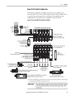
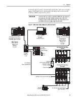
In this example, a non-safety controller makes the Motion-only connection and a
separate GuardLogix safety controller makes the Safety-only connection with
2198-H
xxx
-ERS2 integrated safety drives.
Figure 11 - Motion and Safety Configuration (multi-controller)
IMPORTANT
If two controllers are used in an application with Motion-only and Safety-
only connections, the Safety-only connection must be a 1756-L7
x
S
GuardLogix safety controller and the Motion-only connection must be a
ControlLogix 1756-L7
x
or CompactLogix 5370 controller.
1606-XL
Po we r S u p p l y
Input
Allen-Bradley
LNK1LNK2 NET OK
EtherNet/IP
1
2
LNK1LNK2 NET OK
EtherNet/IP
1
2
1585J-M8CBJM-
x
Ethernet (shielded) Cable
GuardLogix 1756-L7
x
S Controller
Logix Designer
Application
(version 24.0 or later)
AC Input Power
2198-H
xxx
-ERS2 Servo Drives
(top view)
2198-H
xxx
-ERS2 Servo Drives
(front view)
Digital Inputs to Sensors and Control String
1606-XL
xxx
24V DC Control, Digital Inputs,
and Motor Brake Power
(customer-supplied)
Kinetix VP
Servo Motors
2198-CAPMOD-1300 Capacitor Module
(optional component)
1734-AENTR
POINT Guard I/O
EtherNet/IP Adapter
1783-BMS
Stratix 5700
Switch
CompactLogix 5370 Controller or
ControlLogix 1756-L7
x
Controller
(ControlLogix controller is shown)
Motion Program
Module Definition
Configured with
Motion only
Connection
Safety Program
Module Definition
Configured with
Safety only
Connection
Safety
Device


