


216
Rockwell Automation Publication 2198-UM001D-EN-P - May 2014
Appendix C
Sizing Multi-axis Shared-bus Configurations
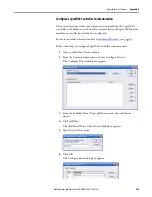
Shared AC/DC Configurations
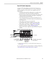
In a shared AC/DC configuration, the first (leftmost) drive receives AC input
voltage. The shared-bus connection system extends the AC and DC bus to all
downstream drives:
•
All drives are configured in the project file as Shared AC/DC drives.
•
Drives must be of the same power rating (catalog number).
•
Shared AC/DC configurations support Bulletin 2198 capacitor modules
•
Total available converter power is derated by 30%.
•
The maximum number of drives configured as Shared AC/DC is
described in
Table 87
.
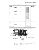
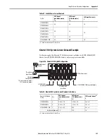
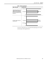
Table 87 - Shared AC/DC Panel Layout
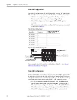
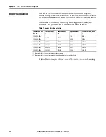
Figure 101 - Typical Shared AC/DC Configuration
For an example shared AC/DC installation with additional details, refer to
Typical Shared AC/DC Installations
Drive Cat. No.
Frame Size
Drives Configured as Shared AC/DC, max
(1)
(1) For Bulletin 2198 capacitor module maximum values, refer to the Kinetix 5500 Capacitor Module Installation Instructions,
publication
Number of Capacitor
Modules, max
2198-H003-ERS
x
1
8
0
2198-H008-ERS
x
1
2198-H015-ERS
x
2
4
4
2198-H025-ERS
x
2198-H040-ERS
x
2198-H070-ERS
x
3
2
4
Bonded Cabinet
Ground
Three-phase
Input Power
Kinetix 5500 Servo Drives
(top view)
24V Input
Control Power
DC Bus Connections
2198-CAPMOD-1300 Capacitor Module
(optional component)