162
Rockwell Automation Publication 2198-UM001D-EN-P - May 2014
Chapter 9
Kinetix 5500 Safe Torque-off - Hardwired Safety
Safe Torque-off Connector
Data
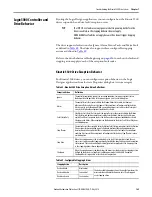
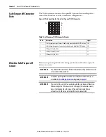
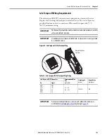
The 10-pin connector consists of two parallel 5-pin rows for cascading safety
connections from drive-to-drive in multi-axis configurations.
Figure 69 - Pin Orientation for 10-pin Safe Torque-off (STO) Connector
Table 75 - Safe Torque-off (STO) Connector Pinouts
Wire the Safe Torque-off
Circuit
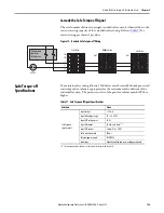
This section provides guidelines for wiring your Kinetix 5500 safe torque-off
drive connections.
Pin 1
SB+
SB-
S1
SC
S2
STO Pin
Description
Signal
1
Safety bypass plus signal. Connect to both safety inputs to disable the STO function.
SB+
2
Safety bypass minus signal. Connect to safety common to disable the STO function.
SB-
3
STO input 1 (SS_IN_CH0).
S1
4
STO input common (SCOM).
SC
5
STO input 2 (SS_IN_CH1).
S2
IMPORTANT
The National Electrical Code and local electrical codes take precedence over the
values and methods provided.
IMPORTANT
To improve system performance, run wires and cables in the wireways as
established in
IMPORTANT
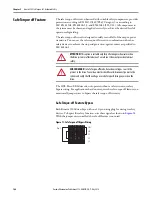
Pins 1 and 2 (SB+ and SB-) are used to disable the safe torque-off function.
When wiring to the STO connector, the 24V supply (for an external safety
device that triggers the safe torque-off request) must come from an
external source, otherwise system performance is jeopardized.


